Hexagon Measurement SystemsNo matter what Hexagon measurement equipment or software you use, we want to hear your ideas and suggestions on how we can improve.
Thanks for your assistance in helping us shape the future. |
|


 Add animation speed slider to lower of window for offline play back

2020 R2 Profile - CAD graphic analysis improvement
In 2020 R2, the calculations/interpretations of profile tolerances have changed. The idea now, for a unilateral tolerance, is that the tolerance zone is offset from the nominal surface an appropriate amount and the zone is expanded/contracted until the surface is "snug".
I created a simple example. Offline, I created an external cylinder. I requested the profile of the surface with [.xxx U 0]. I turned on CAD graphic analysis and the tolerance zone is still centered on nominal. What's worse is that the deviation shows toward the wrong extreme of the zone.
Can this feature be improved so that the graphic analysis of the zone is shifted and the deviation can be shown properly?
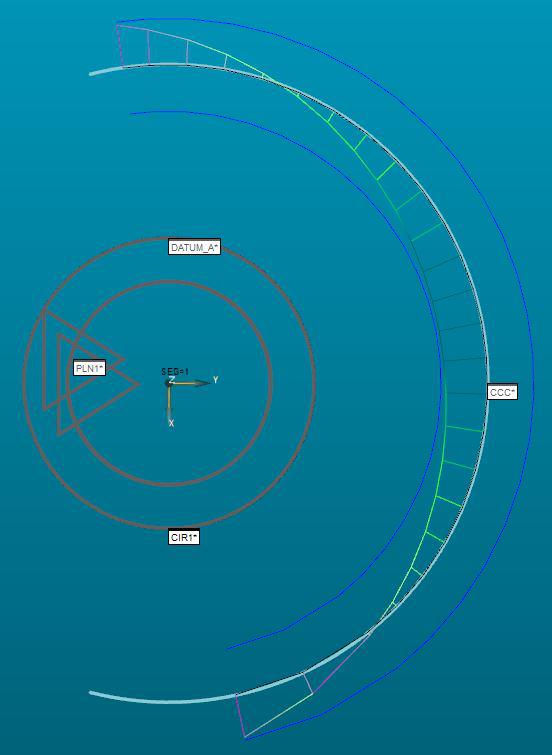
As you can see, at [.xxx U 0], the outer edge would be at the extreme outer edge of the zone. PC-DMIS is showing it at the inner edge.

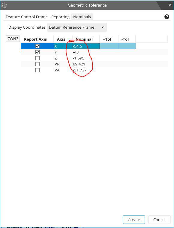
Bring back the ability to edit nominal values in Geometrical Tolerance 2020 R2
Sometimes TED from drawing not fit with model.
It was easy to edit this if necessary on Xact / Geometric Tolerance field.
Unfortunately strange decision to disable this feature in 2020R2....

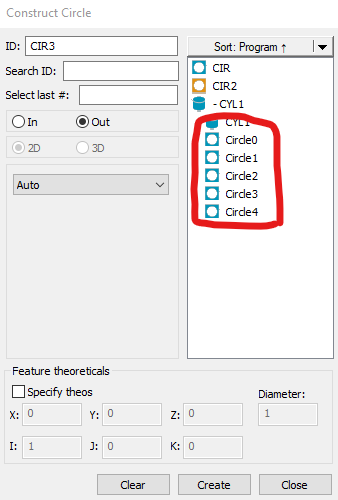
Individual features inside loops selectable in constructions and dimensions
When using loops, anything inside (such as features, dimensions, etc.) must be explicitly typed and named with the array number of the loop iteration, as shown in this example:
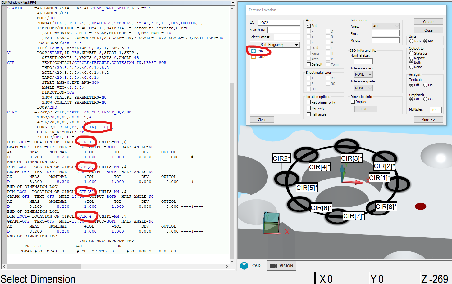
I would like to be able to select the looped features, similar to how the Auto Cylinder Concentric Scan has individual circles that can be selected. This could be based on the loop number parameters, or perhaps the loop would need to be executed to create those looped features?

Change the "Close" menu option to "Save and Quit"
Change the "Close" menu option to "Save and Quit".
This would be much more clear in what is happening.
Creation of "mirrored" points
Idea spawned from the user forum, recently from this discussion:
The longing for a function like this has been around for a long while. Basically what it should do is to create a second vectorpoint based on the vector from the first auto vectorpoint and place that second vectorpoint on the CAD surface that the first vectorpoints vector will intersect/hit. If you don't have CAD, the possibility to control the distance between the points must exist for it to be useful without CAD.
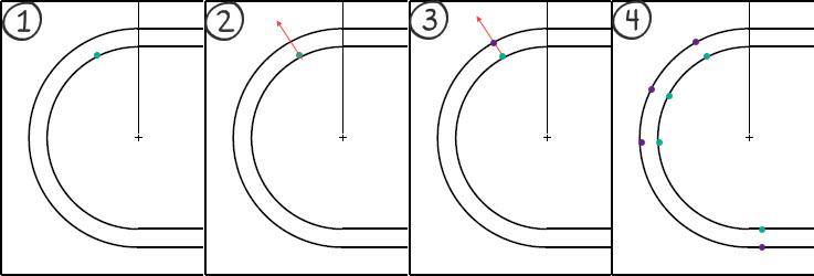
Example of using the function when measuring a groove:
(1) The function should use a "simple" auto vectorpoint as start where we place the vectorpoint at our intended position
(2) The vector of this vectorpoint is used to find the closest CAD surface along the points vector
(3) The new - or "mirrored" - vectorpoint is created on the CAD surface using the vector from the CAD surface
(4) This way we can create "perfectly" opposite points along the groove
This is not just applicable for grooves, but also for opposite planes where we want to create a plane out of the midpoints of the opposite planes - for this we need to be able to place the hits for the planes opposite each other. It is doable today, but very tedious and a function like this would ease the process.

Colour change of points selected for construction
Lets say we have a measured cad model with a load of points taken on it. These points are coloured black on the model.
For eg.
I need to create a plane using some existing points.
From the construction toolbox I choose the plane option and I select the relevant points I need to create the plane.
After selection of these points they still remain coloured black.
Is there a way to make the selected points a different colour, so as to make identification easier, that I have selected the correct points off the model?

Increment Moves with Virtual Machine
Be able to use Increment Moves with Virtual Machine when executing paths and for collision detection.

Provide tolerance zone visualization
Show tolerance zone visualization with DRF animation of GDT constraints
PC-DMIS in one language, the report in another
I am running PC-DMIS with swedish language setting and thus, the report is also in swedish. However, it would be optimal if I could change the report template language to english - just for the report as we have customers all around the world.
In order to that today, I'd have to either run PC-DMIS in english (all the time) or change language, start PC-DMIS, open my program and print the report.
Would it be possible to add the possibility for the report templates to use a different language (other resources from the .dll's) template only for printing?
Customer support service by UserEcho