Hexagon Measurement SystemsNo matter what Hexagon measurement equipment or software you use, we want to hear your ideas and suggestions on how we can improve.
Thanks for your assistance in helping us shape the future. |
|


 I material specific illumination calibration that is interchangeable.
I would like to have the ability to change the illumination calibration without having to re-calibrate the illumination when I inspect a different type of material. At this time, if I calibrate the illumination to one type of material, then I can not use the same calibration on a different type of material as effectively. I would like to be able to toggle between the illumination calibrations.

Add the ability to resize report snapshots

Changing the vector approach on a Circle
It would be nice to add a 3d vector approach in auto circle, to measure circles on cone, sphere... without doing it by autovector points.

I would like to be able to change a contact auto feature into a vision one (and vice versa) without having to delete the feature and recreate it
It would be a good time saver to not need to reprogram if there was a toggle parameter in the edit window for auto features for sensor type

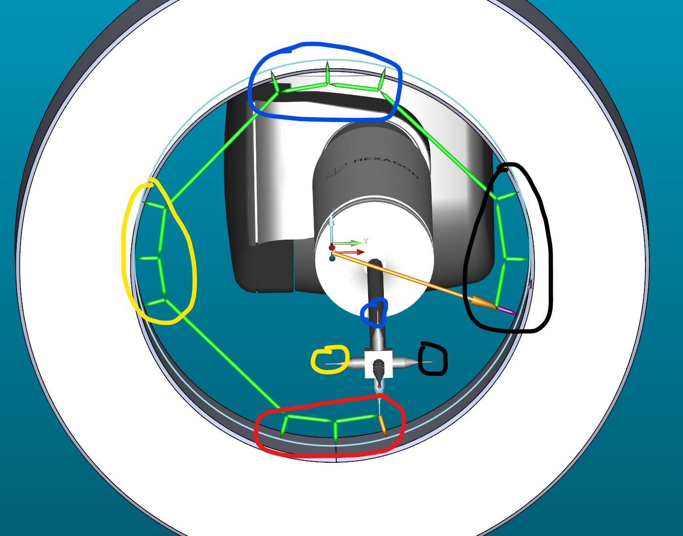
Auto Feature Circle for Star probe with 4 tips
Measuring a circle with 4 tips
auto feature circle

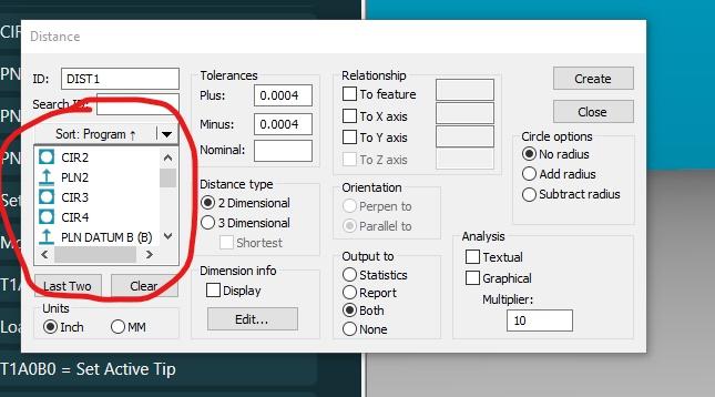
Ability to resize Feature ID List in Distance Dimension Dialog
My work would be much more efficient if I could resize the "Distance" dialog box, specifically the feature ID's list. Currently I can only see 5 feature ID's at a time. When I don't know the names of all the features, or I can't find it in the cad model display, being able to see a larger portion of the list here would be great because I know approximately where or with what other features it is. Most of the time I'm working on parts with hundreds of features.

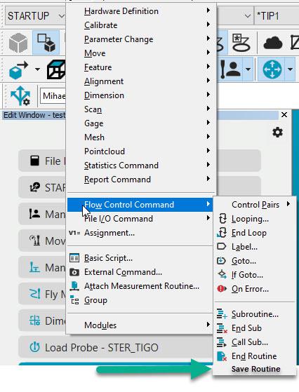
Save function as a PC-DMIS Command
As a PC-DMIS user, it would be an advantage to have a save function in PC-DMIS. Sometimes users are using VB to save the measurement routine. It would be nice if there is a function in PC-DMIS to have a commando in your measurement routine which functions as a Save Routine.

Report concave/convex condition of planes
ability to evaluate if a plane is either concave or convex.

Protected measuring routines
We need a possibility that an user can only open the measuring routine (.PRG) for execution. User in that case means also an operator with full PC-DMIS access and administrator privileges.
Here is the story:
- Customer has 2 Leica trackers from us with PCDMIS.
- Customer constructs big machines for producing car tires. At several moments they measure the setup from their machine with the tracker. Works all fine.
- Next step: if they sell a VMI machine to a customer they think about also selling a Leica Tracker with PC-DMIS as a kind of measuring tool for their customers.
- They create the .PRG, and want that the routine can only be run in Operator Mode. Reason: they do not want that their customers can edit the original .PRG
- Note: the protected mode in PC-DMIS is not an option.
Another example is the ISO acceptance routines. We have to make sure that they can't be changed.

Adjustable feature selection box.
When constructing or dimensioning, the feature selection box should be adjustable in size to see more features or full feature identification for easier selection.
Customer support service by UserEcho
