Hexagon Measurement SystemsNo matter what Hexagon measurement equipment or software you use, we want to hear your ideas and suggestions on how we can improve.
Thanks for your assistance in helping us shape the future. |
|


 Auto Planes
When using an auto plane, we would like to see the option for start points and end points for the plane, as manipulating the points manually around other features can sometimes be difficult.

Measure in 3D-model like CAD-software
Make a function that can measure dimensions in a 3-model like the same way as CAD-software can. Only to know how big some geometry is, or to check something. This can be usefull, because nowadays many drawings are minimum dimensions drawings.

Color code for tolerances
I suggest the software recognizes the color of the surfaces the points are applied to.
When we create dimentions, instead of adding the tollerance for each point (or group of points), we select a color code (that has been sorted out by our engenieering department) and the tolerances are applied considering the CAD surface color and which tolerance that color represents on my color code.

Min/Max reporting for multi-times hole pattern for size and true positions
Many times we have 25 to 100 x's size and location callouts for pattern of holes. It would be nice to have PC-DMIS be able to output Min/Max GeoTol values without hard coded variable arrays.


Change the "Close" menu option to "Save and Quit"
Change the "Close" menu option to "Save and Quit".
This would be much more clear in what is happening.
PROBE CALIBRATION
Add a key in the calibration area where you can save and import a list of angles because every time you create a probe you have to start from zero.

Easy way to populate results in excel based first article travelers
Looking for a way to populate results in specific custom order in Excell based first article travelers.

Remembering past measurements
Now PC-DMIS remembers only measurements made on the last part. A lot of time I need a complete data of part that was measured in past. It could be set to remember last xx measured parts. I know that Calypso has this feature.

Please take a look at the Package Measurement Routine functionality in PC-DMIS 2026.1.
DRF feature construction option(s) - relative to other features/datums
Add options to construct Datum features in such a way that they reflect the standard.
Example - Datum A is a Plane, and Datum B is a cylinder bore nominally perpendicular to the plane.
As per both ISO and ASME standards, Datum B would be a Max Insc Cylinder Perpendicular to Dat A.
It's easy enough to construct a Max Insc cylinder, but this wouldn't be forced perpendicular to the plane, currently you'd have to measure it as a series of circles, then construct a Max Insc Circle in the correct workplane after levelling to Dat A.
See bottom image for example (image shows shaft not bore but principle is the same).
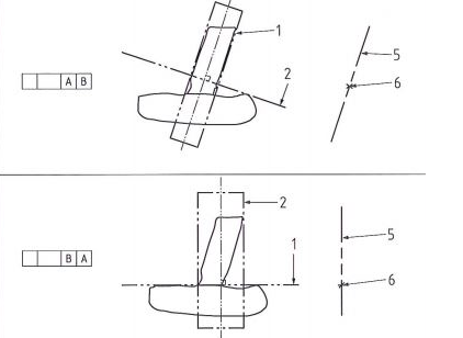
Like wise construct a datum plane from a measured plane relative to another feature (Top image)
Customer support service by UserEcho
