Hexagon Measurement SystemsNo matter what Hexagon measurement equipment or software you use, we want to hear your ideas and suggestions on how we can improve.
Thanks for your assistance in helping us shape the future. |
|


 Single click Auto circle by using star dia probe
In fixed probe head cmm if single click we pick the auto circle by using star dia probe it would be very easy to measure the circle, the same option available in quindos software .please try to implement the same in PCDMIS.

Creation of "mirrored" points
Idea spawned from the user forum, recently from this discussion:
The longing for a function like this has been around for a long while. Basically what it should do is to create a second vectorpoint based on the vector from the first auto vectorpoint and place that second vectorpoint on the CAD surface that the first vectorpoints vector will intersect/hit. If you don't have CAD, the possibility to control the distance between the points must exist for it to be useful without CAD.
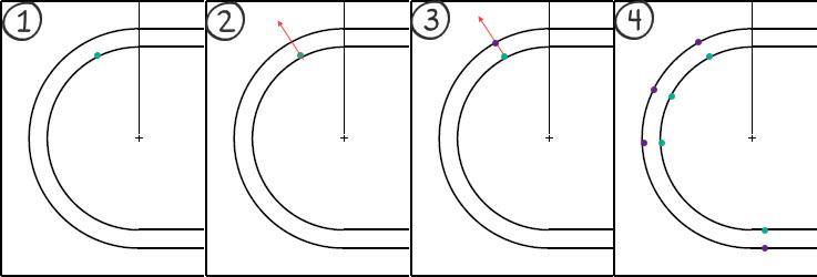
Example of using the function when measuring a groove:
(1) The function should use a "simple" auto vectorpoint as start where we place the vectorpoint at our intended position
(2) The vector of this vectorpoint is used to find the closest CAD surface along the points vector
(3) The new - or "mirrored" - vectorpoint is created on the CAD surface using the vector from the CAD surface
(4) This way we can create "perfectly" opposite points along the groove
This is not just applicable for grooves, but also for opposite planes where we want to create a plane out of the midpoints of the opposite planes - for this we need to be able to place the hits for the planes opposite each other. It is doable today, but very tedious and a function like this would ease the process.

Colour change of points selected for construction
Lets say we have a measured cad model with a load of points taken on it. These points are coloured black on the model.
For eg.
I need to create a plane using some existing points.
From the construction toolbox I choose the plane option and I select the relevant points I need to create the plane.
After selection of these points they still remain coloured black.
Is there a way to make the selected points a different colour, so as to make identification easier, that I have selected the correct points off the model?

Increment Moves with Virtual Machine
Be able to use Increment Moves with Virtual Machine when executing paths and for collision detection.

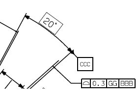
Provide tolerance zone visualization
Show tolerance zone visualization with DRF animation of GDT constraints
PC-DMIS in one language, the report in another
I am running PC-DMIS with swedish language setting and thus, the report is also in swedish. However, it would be optimal if I could change the report template language to english - just for the report as we have customers all around the world.
In order to that today, I'd have to either run PC-DMIS in english (all the time) or change language, start PC-DMIS, open my program and print the report.
Would it be possible to add the possibility for the report templates to use a different language (other resources from the .dll's) template only for printing?

Continuing development of Textonly Legacy Reporting
To have Legacy Textonly report supporting PC-DMIS Dimensions functionalities, or to have a similar report that is true text report and not just pictures that look like text.


Datum definition allow multiple characters
Allow to add multiple characters on a datum definition not only 2.

New point construction method: "high point"
Finding the "high point" of a feature or scan is a very common measurement task.
In pc-dmis, this is a complex task, that requires an understanding of array indexing, and significant manual entry into a generic feature. It is prone to error, is very time consuming, and for users never exposed to a programming language it's a complete non-starter.
A simple, interface-based point construction method could be added to address these issues. The new method should be based on the DMIS method "CONST/EXTREM". It is very complete, and since pc-dmis imports DMIS code - it only makes sense to have a 1 to1 mapping of the DMIS definition.
Сервис поддержки клиентов работает на платформе UserEcho
