Hexagon Measurement SystemsNo matter what Hexagon measurement equipment or software you use, we want to hear your ideas and suggestions on how we can improve.
Thanks for your assistance in helping us shape the future. |
|

 Integrated PC-DMIS QDAS converter
It would be nice to have PC-DMIS QDAS converter integrated inside PC DMIS, with intuitive K-Fields set-up menu and possibility to export all PC DMIS Dimension functionalities to .DFQ files

Ability to manage all reports
If i have to measure 10 same parts, it will be great if there is ability to edit reports from 1 to 10, even if i executed program for each. For now, it's only "View last execute report mode"

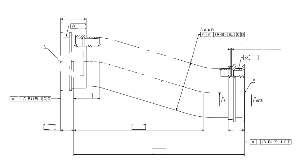
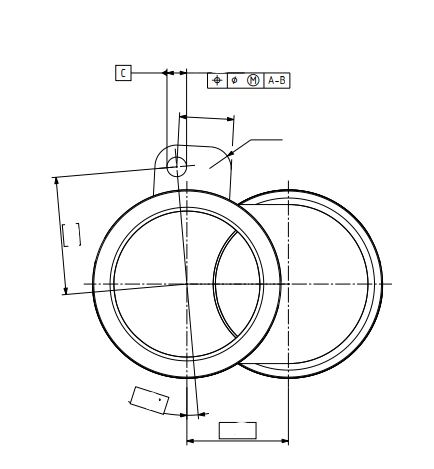
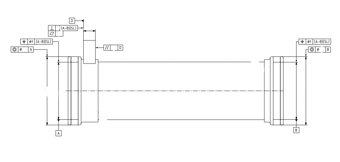
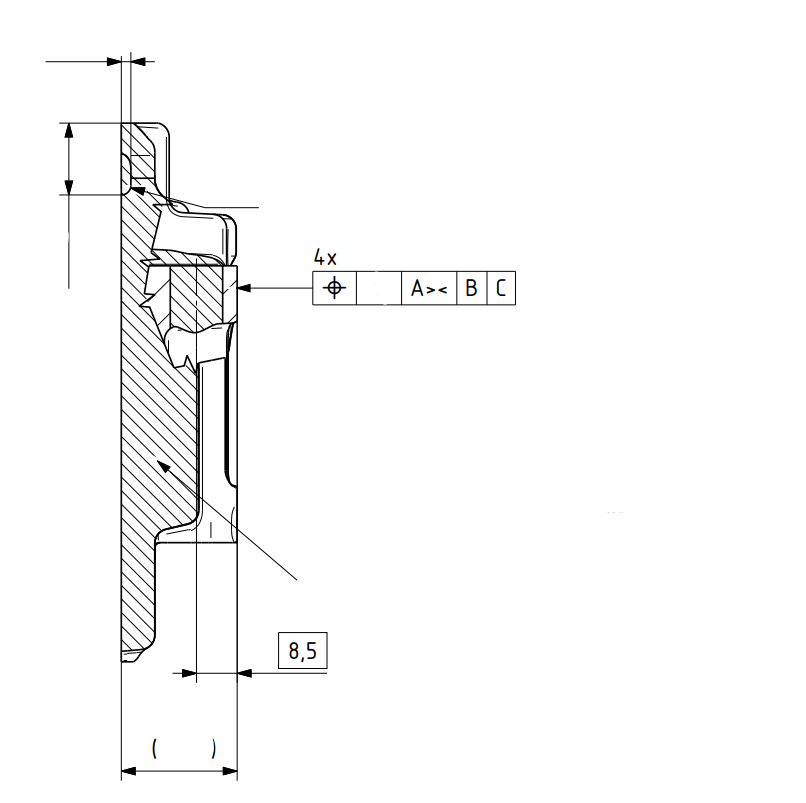
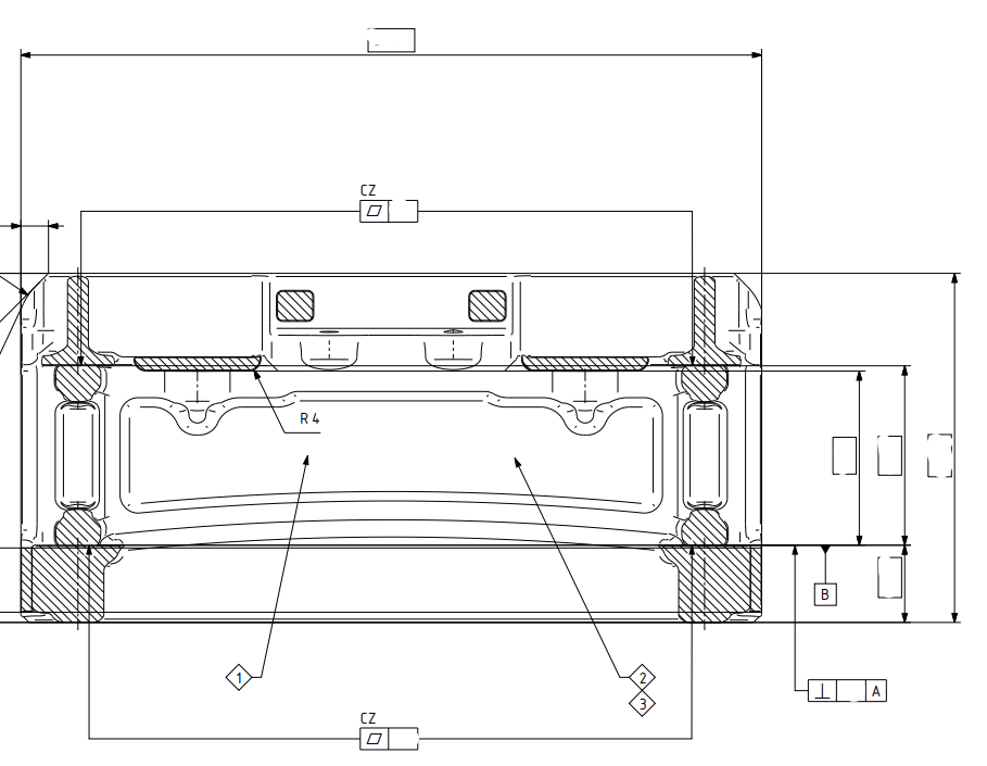
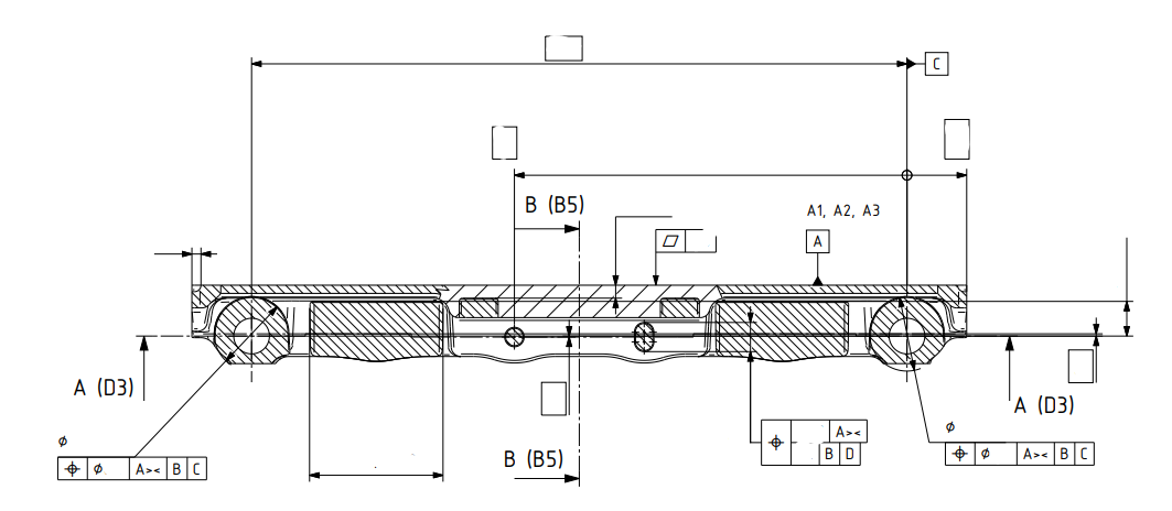
Add ISO 5459 modifers ><, [SL], [PL], [PT]
The "new" modifiers in ISO 5459 are becoming more popular and relevant in some technical drawings. Most common are ><, [SL], [PL] and [PT]. Some of Hexagons/PC-DMIS competitors are already starting to introduce these modifiers. If PC-DMIS wants to be on top of the competition within ISO GPS, its time to start introducing things like these. Its quite hard to evaluate properly according to standard without these modifiers.
Added some picture of examples.

Add the axis and workpiece temperatures to the "probe reading" window
It is often useful to know the temperatures of the axes and the workpiece in real time without having to call up the thermal compensation command.
PC-DMIS does not have a window that displays these temperatures in real time.

Confirm Tracefield pop-ups with the green check controller button
You can confirm most pop-ups with the controller, except for the Tracefield window. It's a small quality of life thing.
Allow combination of cylinder + width or circle + width for common datum in PC-DMIS
I want the combination of cylinder + width and circle + width to be allowed to be used as common datum. Currently it is not. According to ISO 5459 rules, this would be equal to be using the [DF]-modifier when the datums are separated. While using DF is fine, allowing the common datum combination removes the risk of unnecessary questions or discussions on how the final report should look, making the report mirror the requirement in the drawings.

Add the ability to toggle the measurement order/path of auto cylinders for shallow diameters
Currently, PCDMIS measures by "rows" following along the diameter before moving up or down the height of the cylinder once it has completed the circle at that height.
It would save a lot of time if we could toggle to measure by “columns” first, measuring up or down the length of the cylinder first before moving radially to the next part of the cylinder.
Adaptive Cylinder Line Scans measures with a very similar path on a scanning CMM.
This could drastically speed up measurement time on parts with large diameters but shallow lengths.
CMM Manager has a feature like this, and it cut 30 seconds off of the runtime of one part.
Automatic settings for UPR and cutoff wavelength
I absolutely love the automatic scanning parameters based on size/position/form in PC-DMIS. It's a set it, forget it thing for me. However, when it comes to the gaussian filter settings, things can get complicated. The general rule is that you need at least 7 points per undulation/wavelength. A lot of the literature talks about a given UPR/wavelength, and then changing the number of points scanned accordingly. However, the point density is automatically determined based on size/position/form, and you have little influence on the scanning path. The number of points therefore is set, and you need to change the filter settings accordingly. I use a little Excel sheet where I can enter the point density per millimeter that PC-DMIS has cooked up for me (you also need to enter the diameter for round features). The sheet will spit out the filter settings based on 8 points per undulation/wavelength (1 more than the minimum). This has worked very well for me, but it's a lot of work to set up for each feature. It's also easy to forget. Especially when scanning large diameters this can cause problems. Filtering a 500mm diameter with a point density of 6 with only 15 UPR is not ideal...
In summary: I'd love to see some kind of optional setting where you can change the filter strength based on the points per undulation/wavelength, rather than some absolute value that doesn't tell you anything without knowing the scanning density and diameter of the feature. 7 would be the minimum setting, to help prevent novices from filtering wrong. People like myself could set it to 8 and make it default. If you need a more aggressive filter, just increase the points per undulations/wavelength. Or just enter the UPR or wavelength manually, if that's your jam.

Traffic Light system for Programs - Proven - Unproven/Rev change - Quarantined
Hi Could a traffic light system be implemented to see what level a program is at. currently I would just do this through naming convention of the program but this could end up me having multiple programs that aren't necessary.
Green - Proven, Up-to current revision
Amber - Un-Proven / Revision Change needed
Red - Unproven Program / Quarantined
Fixture Builder turn off on snapshot when not showing in graphic display window
Customer support service by UserEcho