Hexagon Measurement SystemsNo matter what Hexagon measurement equipment or software you use, we want to hear your ideas and suggestions on how we can improve.
Thanks for your assistance in helping us shape the future. |
|


 Vectors of deviation in CAD protocol
Hello,
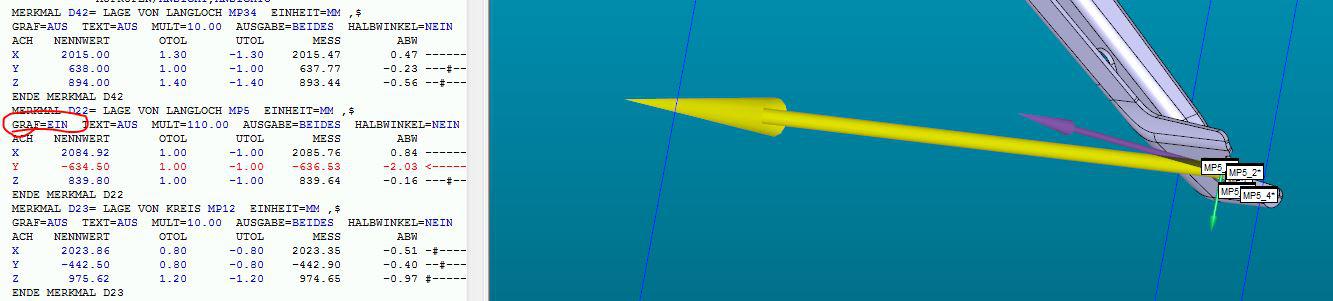
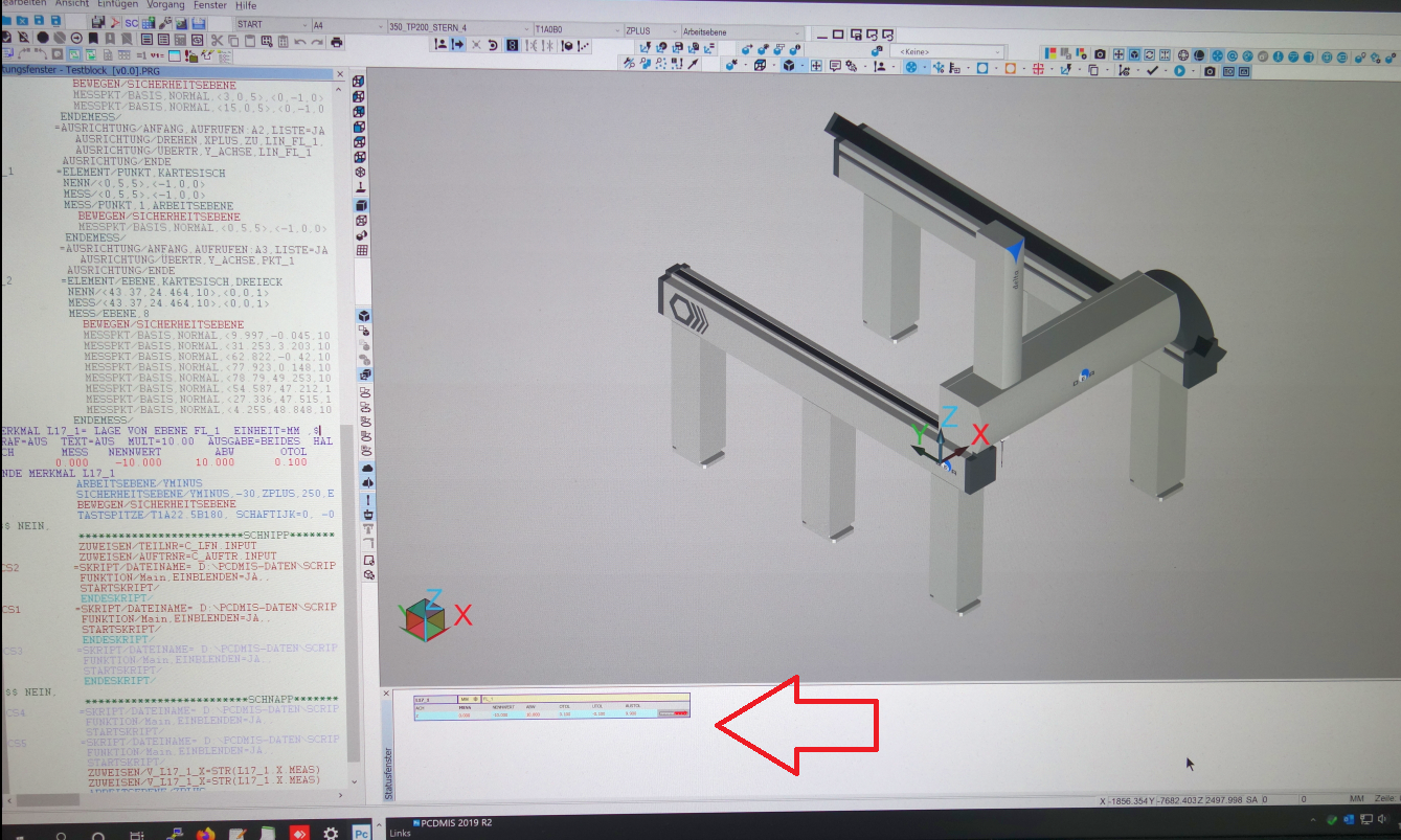
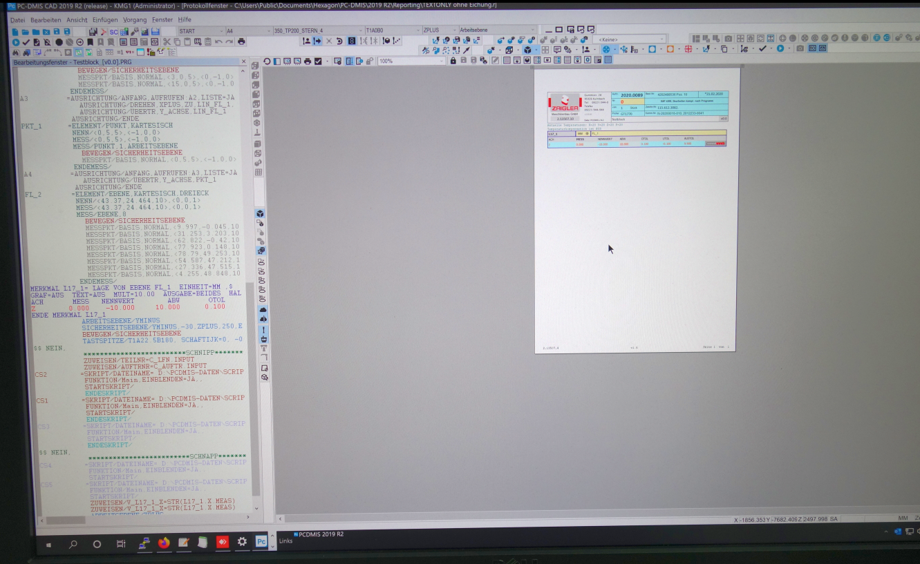
we need to have the option to show the vectors of the deviation in our protocol.
It is possible in the graphical window in PC-DMIS, so why isnt it possible in the "CADONLY" protocol e.g.?
Here is a screenshot what I mean:
Thanks in advance

2021.1__Add unequal tolerance zones for analysis view command
Using 2021.1, an "analysisview" command of a feature control frame that uses the "U Modifier" will ONLY allow us to put on the inspection report an "analysisview" of a BILATERAL tolerance band.
Please add the capability for us to show the tolerance band as UNEQUAL.

summary view, color scheme, similar to edit window colors
add a color scheme to the summary view, similar to the edit window color scheme that can be saved and recalled.


Datum feature in edit feature window
Add a feature in the screen for editing a feature (plane, cylinder, etc) to assign it as a datum instead of going through dimension datum screen and/or gd&t dimension.
Enable "To Points" toggle in all auto-features
Regarding the "To Points" toggle in the auto-feature dialogue box..
Would it be possible to make this toggle work for every type of auto-feature?
Right now, you can only use "To Points" on autocircle, autoplane, and autocylinder. The toggle is "grayed out" for lines, cones, spheres, etc. Adding this functionality would be a good enhancement IMO.
Thanks for your time,
-Dan

Move probe to center of calibration sphere before next rotation
In the calibration cycle, the possibility that the probe moves to the center of the calibration sphere before the next rotation move. This is useful if using a small CMM. It saves room and the eliminates the chance of a collision with the CMM support legs.

Scale behavior with 4k resolution on monitors should be reworked
We have new workstations with 4k monitors but the behavior of PCDMIS was disappointing while switching to the desired resolution with suitable scaling for our monitors.
We are using PCDMIS 2019 R2, with NVIDIA Quadro P4000
Here some screenshots for demonstration
Current Windows settings with 1920x1080 / 100%.
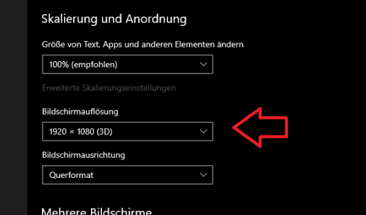
So it looks now with loss of edge sharpness, which has particularly bad effects on the graphics window.
This is our solution at the moment, but the screen is slightly blurry.
We had imagined differently, especially working with CAD models.
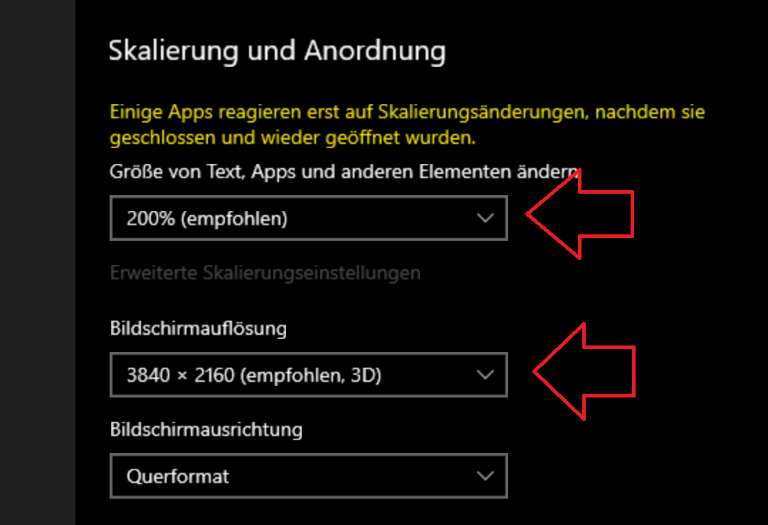
If we set the better resolution and the appropriate scaling for our monitors, it looks like this:
Now switch to
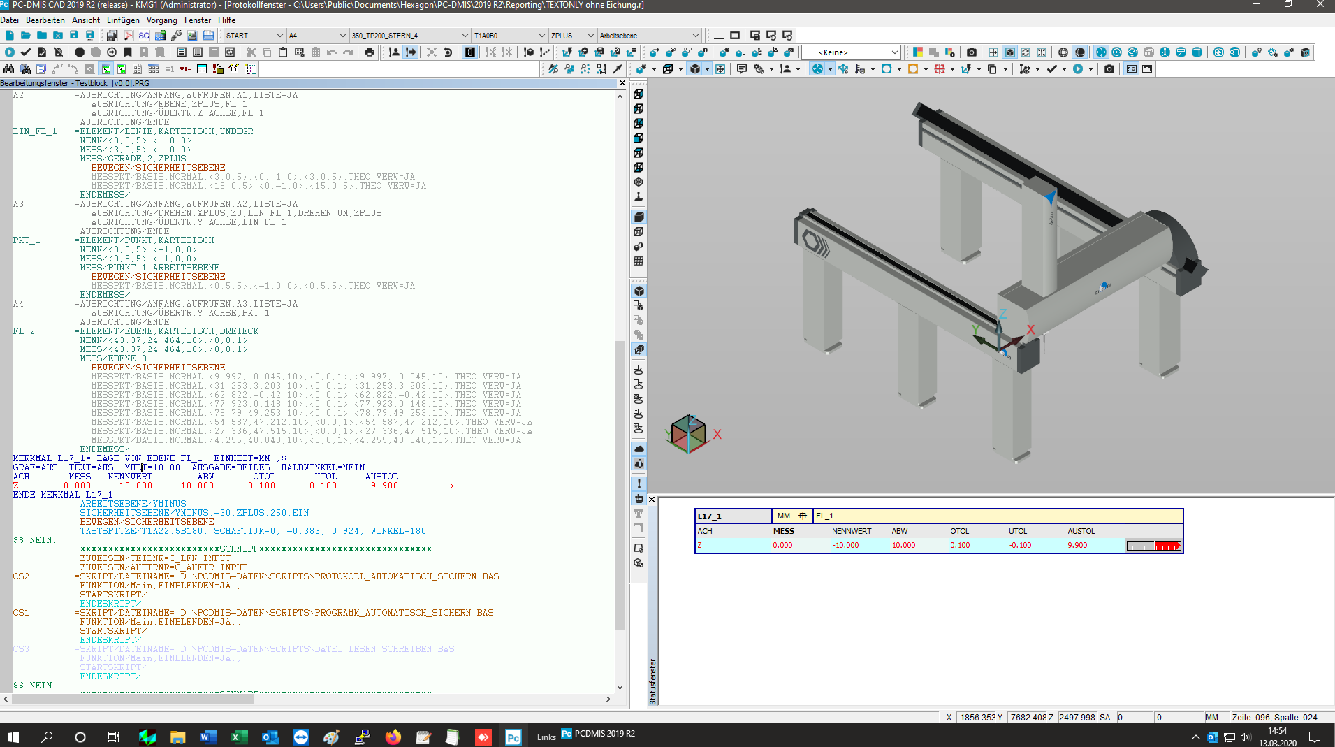
now it looks so after PCDMIS restart on the same monitor
Font and icons seems to be ok but the report window is not really usable without up scaling.
With up scaled settings e.g. 200% in the report window it looks not really nice, moreover the labels inside status
window are not scalable. You need a magnifying glass for this. ;-)
Please fix this behavior. Thanks

I would like to calculate the area focus and the area of scans
We have irregular contours (turtle, Easter eggs, seahorses) and need the area and their from closed scans.
Our competitors are already working with this for a long time.

Customer support service by UserEcho
