Hexagon Measurement SystemsNo matter what Hexagon measurement equipment or software you use, we want to hear your ideas and suggestions on how we can improve.
Thanks for your assistance in helping us shape the future. |
|

 Have the clearance cube wrap around the form of the part instead of a cube that has deadspace in it
This would save lots of time for some parts. Think of it like the shield from the Dune movies. The clearcube should form around the part

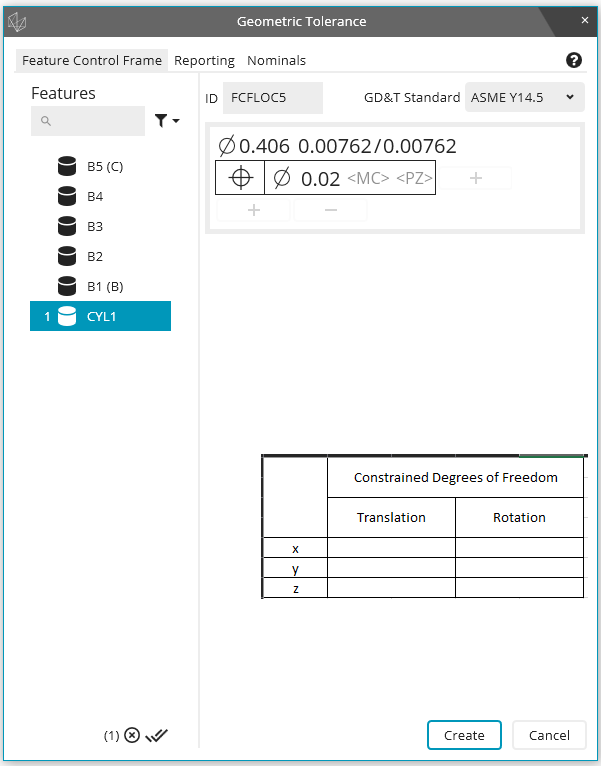
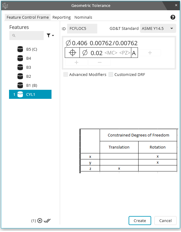
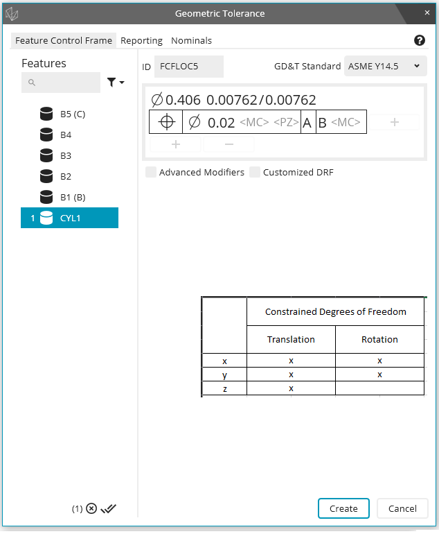
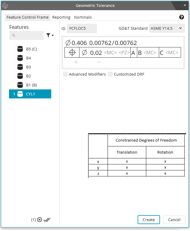
Show constrained degrees of freedom in the geometric tolerance dialog window
It would be helpful to see the actively constrained degrees of freedom as the feature control frame is being built in the geometric tolerance dialog window. As an example, assume I have a primary datum plane (normal Z+), a secondary datum cylinder (axis along Z), and a tertiary datum cylinder (axis along Z). Then, as I build my feature control frame, the geometric tolerance dialog window shows me which degrees of freedom become constrained as the images below show:
Ability to Assign a Dimension as Attribute
I would like the ability to create an attribute dimension, similar to a "Keyed In" dimension that has a non-numerical value of either "PASS" OR "FAIL" and the ability to pass that result to reports or Excel exports. Currently, all defined dimensions are numerical.

Complete autocalibration routine
Autocalibration Currently does not remeasure failed tips. My suggestion is to implement a feature within the Autocalibration routine that allows it to remeasure the tips that failed the standard deviation. As well as adding a feature within the autocalibration code that allows you to select the calibration sphere when the qualtool has been moved only. This would be used for all autocalibration within that code as well but only selected at the beginning of the program to ensure correct vector and size are used. My expectation if this gets implemented is when i leave on Friday, i can start the autocalibration routine and come back on Monday with no tips that have been outside of the standard deviations.

Gerber Format Support
The Gerber format is a standard ASCII format file structure and uses X, Y, Z and I, J, K information that enables data exchange between CAD (development) and CAM (production). It is primarily used in electronic CAD programs (EDA – Electronic Design Automation) to output layout data for printed circuit boards.
We are frequently confronted with this format and here we have a competitive disadvantage compared to providers who can read this format into their measurement software without further external conversion.
It would therefore be desirable to integrate a corresponding import interface into PC-DMIS.

Possibility to scale the size and change the color of type of Annotation Points
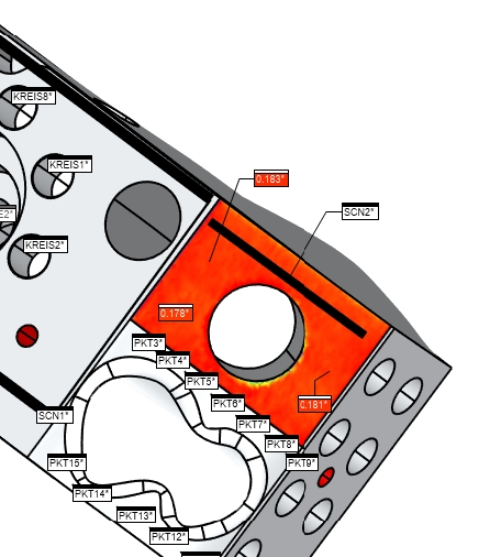
As a PC-DMIS User I would like to have the possibility to enlarge the size of Annotation Points created out of Surface colormaps or Pointcloud colormaps. Sometimes it is very hard to read the value inside of Annotation Points, because they are just too small. Sometimes it is hard to read because you do not have a nice contrast between the Type and the background color. In this case it would be nice if I could change the color of the type.
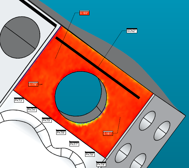
While in Graphic Window the Annotations are good to read, it may be more difficult in Reports, etc.


Individual features inside loops selectable in constructions and dimensions
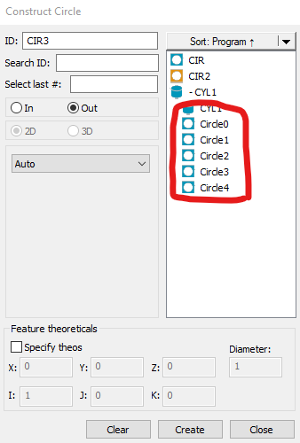
When using loops, anything inside (such as features, dimensions, etc.) must be explicitly typed and named with the array number of the loop iteration, as shown in this example:
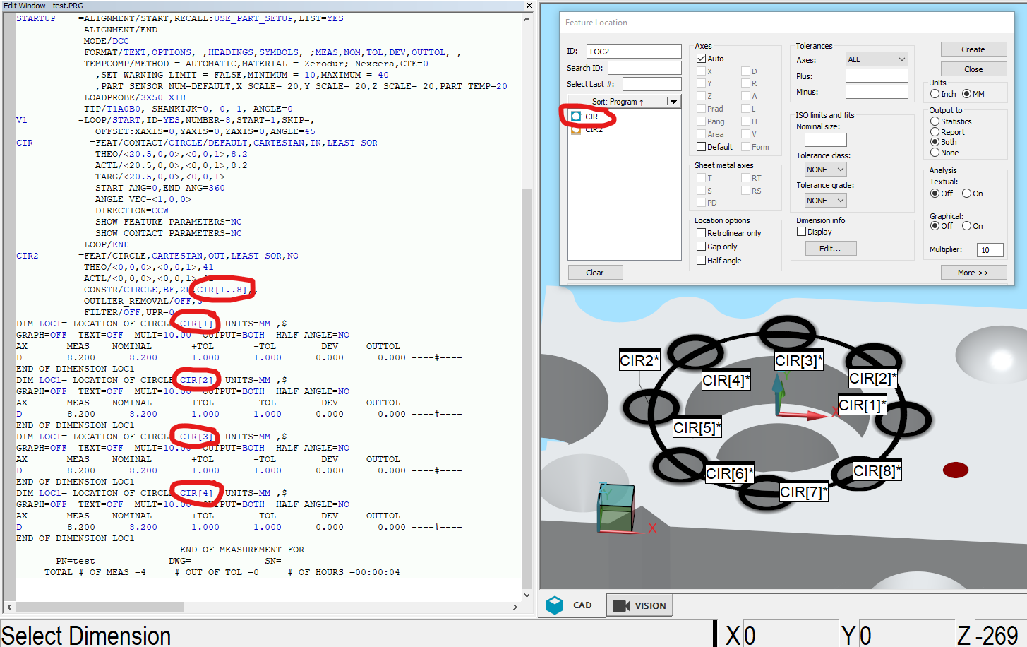
I would like to be able to select the looped features, similar to how the Auto Cylinder Concentric Scan has individual circles that can be selected. This could be based on the loop number parameters, or perhaps the loop would need to be executed to create those looped features?

Single click Auto circle by using star dia probe
In fixed probe head cmm if single click we pick the auto circle by using star dia probe it would be very easy to measure the circle, the same option available in quindos software .please try to implement the same in PCDMIS.
Creation of "mirrored" points
Idea spawned from the user forum, recently from this discussion:
The longing for a function like this has been around for a long while. Basically what it should do is to create a second vectorpoint based on the vector from the first auto vectorpoint and place that second vectorpoint on the CAD surface that the first vectorpoints vector will intersect/hit. If you don't have CAD, the possibility to control the distance between the points must exist for it to be useful without CAD.
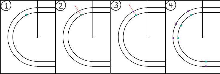
Example of using the function when measuring a groove:
(1) The function should use a "simple" auto vectorpoint as start where we place the vectorpoint at our intended position
(2) The vector of this vectorpoint is used to find the closest CAD surface along the points vector
(3) The new - or "mirrored" - vectorpoint is created on the CAD surface using the vector from the CAD surface
(4) This way we can create "perfectly" opposite points along the groove
This is not just applicable for grooves, but also for opposite planes where we want to create a plane out of the midpoints of the opposite planes - for this we need to be able to place the hits for the planes opposite each other. It is doable today, but very tedious and a function like this would ease the process.
Customer support service by UserEcho