Hexagon Measurement SystemsNo matter what Hexagon measurement equipment or software you use, we want to hear your ideas and suggestions on how we can improve.
Thanks for your assistance in helping us shape the future. |
|

 Ability to manage all reports
If i have to measure 10 same parts, it will be great if there is ability to edit reports from 1 to 10, even if i executed program for each. For now, it's only "View last execute report mode"

 Ability to choose report method from Cartesian to radial or spherical on geometrical results.
We have many drawings that have surface profiles, the dimensions may apply to flat, angles, curved, radial and spherical surfaces which have BASIC controls that when reported, do not match the drawing at all, this is due to the fact that when choosing to report a surface profile, the data shown is in Cartesian and no choice for radial or spherical to report. When programming to create a new coordinate that sets the origin to a location and be able to measure radial points or surfaces, the output data needs to have the relationship to match the drawing call out, this helps with making decision on mold making, machining and or part configuration. Customers also have no correlation of results to drawing, X,Y,Z does not corollate if features are radial or spherical when looking at the surface profile point data to evaluate.

 Traffic Light system for Programs - Proven - Unproven/Rev change - Quarantined
Hi Could a traffic light system be implemented to see what level a program is at. currently I would just do this through naming convention of the program but this could end up me having multiple programs that aren't necessary.
Green - Proven, Up-to current revision
Amber - Un-Proven / Revision Change needed
Red - Unproven Program / Quarantined

 Add an option to toggle off the "smart calculation" for ending offsets of Cylinders and other auto features.
Add an option to toggle off the "smart calculation" for ending offsets of Cylinders and other auto features.

 Remaining Travel + Next Action Display for CMM
I suggest adding a “remaining travel” and “next action” display for the 3D CMM, similar to what we have on CNC lathes and milling machines. This would give a clear overview of where the machine will move next, helping to avoid collisions and making it easier to follow what happens during program runs or teaching.
Thanks for considering this!

 I like to get the actual selected and executed Miniroutine(s) by automation
I like to get the actual selected and executed Miniroutine(s) by automation. A function like GetActiveMiniRoutine() on Part level can be a solution.

 Vision - Possibility to use live view like a projector by using 2D dxf Contour shown in Live Image
When measuring with the optics, it should be possible to superimpose an overlay on the live image.
Similar to a wireframe model or a DXF contour, the lines of the nominal geometries should lie over the camera image.
This allows the operator to visually compare the actual and nominal contours, just like with a projector. Furthermore, the customer wishes to carry out manual measurements in the live view between the nominal and actual contour. Such as distances, angles etc.

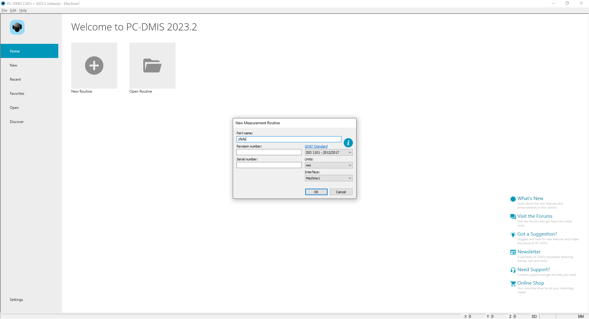
 Why you don´t have a way or option to save a New file choosing by us a other folder?
Good Morning,
In the home page when I create a new file, I can not save my new file routine on a folder choosing by me.
Beacause I think there is a default folder already defined by PC-DMIS, but it is a folder that is located in an APPdata folder. This means we have to copy to the folder we want.
Can you do an improvement so that I can choose a folder to save my file?
Best Regards


 autocalibrate probes within a single routine based on last calibrated date
I'm looking to have an auto calibrate command for all probes/tips within a single routine that have been calibrated outside a specified range. With this, it would also be nice to have a way to see all used probes and tips within the routine without having to go into each probe individually and select mark used. Currently we calibrate probes by opening each probe (F9), selecting mark used and looking at the calibration dates/times. If it has been outside of 24 hours we typically calibrate only the necessary tips. I'd like a way to do this automatically, and to be able to use this command from a form.
Thanks
Customer support service by UserEcho


