Hexagon Measurement SystemsNo matter what Hexagon measurement equipment or software you use, we want to hear your ideas and suggestions on how we can improve.
Thanks for your assistance in helping us shape the future. |
|

 Allow tolerance warning threshold to be configured
UK customer has requested a way in Inspect to specify a % of tolerance, and if dimensions are within tolerance, but above the % of tolerance, they would be marked in yellow on the dimension summary screen at the end of execution.

See CAD model inside Inspect Interface.
Would like to be able to view the CAD model within the Inspect user interface while the program is executing. Similar to the current Operator mode functionality.

Remembering past measurements
Now PC-DMIS remembers only measurements made on the last part. A lot of time I need a complete data of part that was measured in past. It could be set to remember last xx measured parts. I know that Calypso has this feature.

Please take a look at the Package Measurement Routine functionality in PC-DMIS 2026.1.

DRF feature construction option(s) - relative to other features/datums
Add options to construct Datum features in such a way that they reflect the standard.
Example - Datum A is a Plane, and Datum B is a cylinder bore nominally perpendicular to the plane.
As per both ISO and ASME standards, Datum B would be a Max Insc Cylinder Perpendicular to Dat A.
It's easy enough to construct a Max Insc cylinder, but this wouldn't be forced perpendicular to the plane, currently you'd have to measure it as a series of circles, then construct a Max Insc Circle in the correct workplane after levelling to Dat A.
See bottom image for example (image shows shaft not bore but principle is the same).
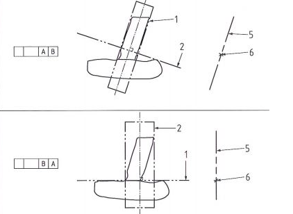
Like wise construct a datum plane from a measured plane relative to another feature (Top image)

Make it possible to re-enumerate feature numbers after program is written/edited.
Your program is finished but some points or features were added and their out of numerical order.
A Re-number feature would put them all in ascending order.

Save the PC-DMIS version/SP/Schema so that we can identify what version of PC-DMIS is needed to open this file.
Can we get some way to record what version/schema of PC-DMIS is required to open a particular PC-DMIS file? With the rolling cutoff and some users having a mix of schema for their routines, I fear difficulties with using the migration utilities in the future.

Add UPR as smart parameter in the measurement strategy editor
As more and more customers are asking us to scan (with a probe) all features, they also got their standards for using the filters in scanning. In those standards, they also ask for a specific UPR which relates to the current diameter. For example, Ø8 and smaller require a UPR setting of 15. Ø8-Ø25 require UPR 50 etc.
I'd like to add this as a smart parameter in the Measurement Strategy Editor to make sure we also use the correct settings.

Have the clearance cube wrap around the form of the part instead of a cube that has deadspace in it
This would save lots of time for some parts. Think of it like the shield from the Dune movies. The clearcube should form around the part
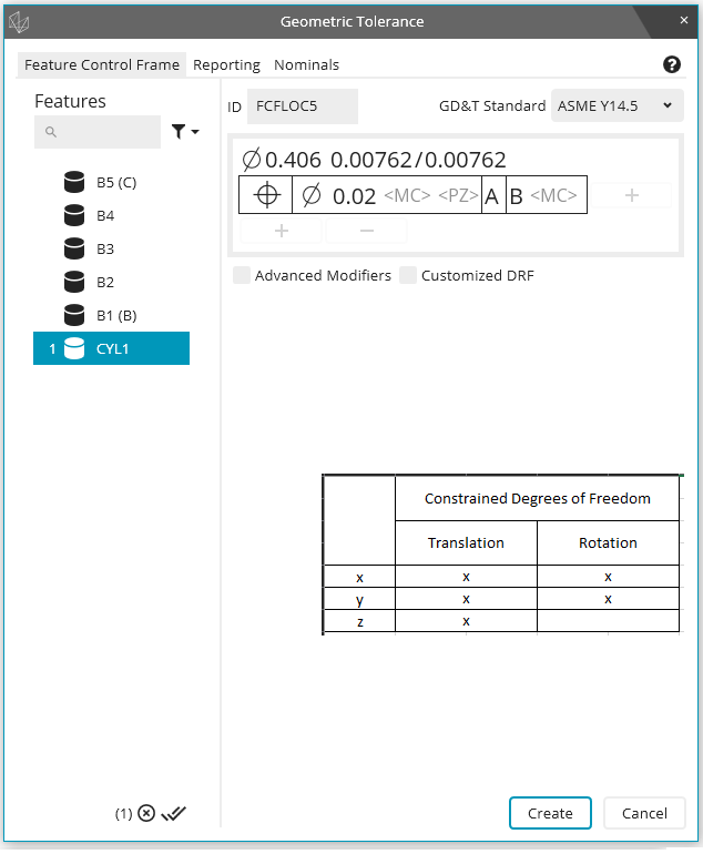
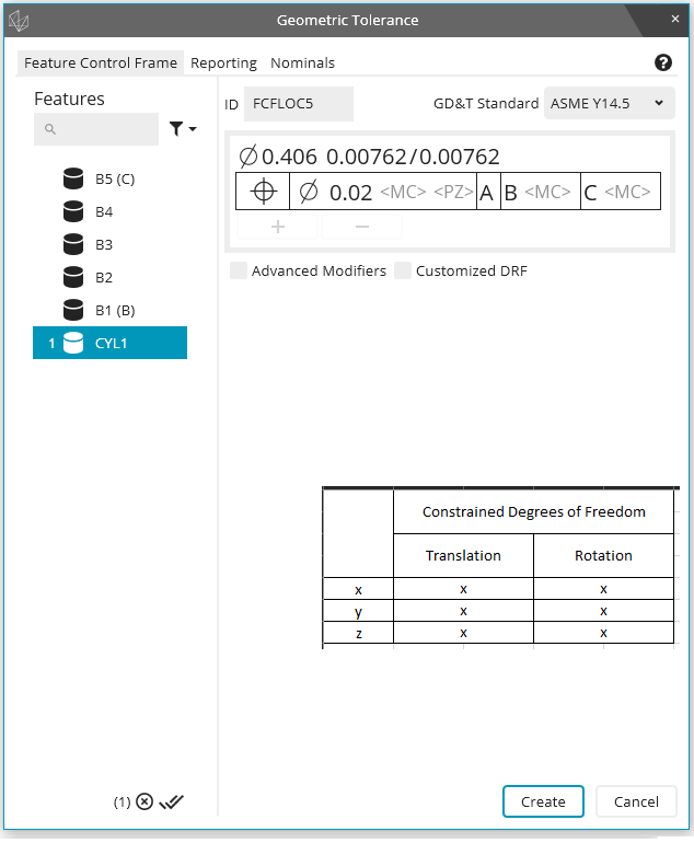
Show constrained degrees of freedom in the geometric tolerance dialog window
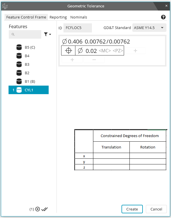
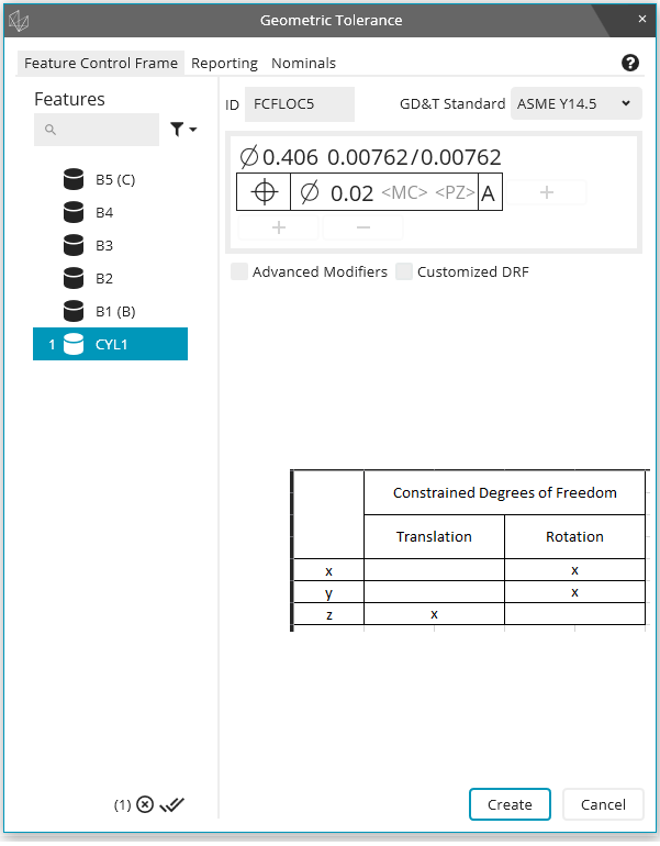
It would be helpful to see the actively constrained degrees of freedom as the feature control frame is being built in the geometric tolerance dialog window. As an example, assume I have a primary datum plane (normal Z+), a secondary datum cylinder (axis along Z), and a tertiary datum cylinder (axis along Z). Then, as I build my feature control frame, the geometric tolerance dialog window shows me which degrees of freedom become constrained as the images below show:
Ability to Assign a Dimension as Attribute
I would like the ability to create an attribute dimension, similar to a "Keyed In" dimension that has a non-numerical value of either "PASS" OR "FAIL" and the ability to pass that result to reports or Excel exports. Currently, all defined dimensions are numerical.
خدمة دعم العملاء من خلال UserEcho