Hexagon Measurement SystemsNo matter what Hexagon measurement equipment or software you use, we want to hear your ideas and suggestions on how we can improve.
Thanks for your assistance in helping us shape the future. |
|

 Analysis view with CAD model
Add functionality to include CAD view with analysis view.

 General Tolerances ISO 2768, DIN 1688, DIN16742, DIN 16901
We have requests from customers that are asking us about different ISO standards : ISO 2768, DIN 16742, ISO 286-1 or DIN 16901. The most common standard which we are finding in technical drawings is ISO 2768.

 Move to toolchanger mount point
The move to the toolchanger mount point should be seperated by the axis like the clearance point
(e.g. Z first, then XY)

 Import/Export Window Layout
It would be nice to have an import / export option for the Window Layout between cmms and Pc-Dmis versions.
Now, after upgrade, I have to create my Window Layout from begining for all machines.

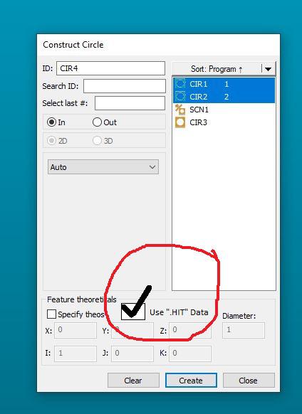
 Add a "use hit data" checkbox in the CONSTRUCTION dialogue box_eliminate the need to "hardcode"
Goal with this post:
SIMPLIFY the feature construction process for things that share a centroid.
Currently:
To CONSTRUCT two or more features together that SHARE A CENTROID, one must:
1) CONSTRUCT desired features into a featureset, click OK....2) Once featureset is in the edit window, switch to COMMAND MODE and then hardcode the ".hit" / ".numhits" into the featureset...3) CONSTRUCT your final geometry out of the featureset.
This works well but is not very user friendly. Takes multiple steps & some typing, is error prone.
Workflow potential using my recommendation:
1) CONSTRUCT desired features into the geometry you need (i.e. if you're constructing two or more radii, go into circle construction..if you're constructing two or more cones, go into cone construction, etc...) & check off a box that says "Use .Hit Data" (or however you guys want to word it), click OK. (at which point the software will do the hardcoding for us and insert the code into the edit window...eliminating a LOT of typing/copying and pasting that A LOT of us do on a daily basis).
Could look something like this:

Software would directly make this code or something similar:
[code]
CIR1 =FEAT/CONTACT/CIRCLE/DEFAULT,CARTESIAN,IN,LEAST_SQR
THEO/<0,0,0>,<0,0,1>,2.3622
ACTL/<0,0,0>,<0,0,1>,2.3622
TARG/<0,0,0>,<0,0,1>
START ANG=0,END ANG=180
ANGLE VEC=<1,0,0>
DIRECTION=CCW
SHOW FEATURE PARAMETERS=NO
SHOW CONTACT PARAMETERS=NO
CIR2 =FEAT/CONTACT/CIRCLE/DEFAULT,CARTESIAN,IN,LEAST_SQR
THEO/<0,0,0>,<0,0,1>,2.3622
ACTL/<0,0,0>,<0,0,1>,2.3622
TARG/<0,0,0>,<0,0,1>
START ANG=180,END ANG=0
ANGLE VEC=<1,0,0>
DIRECTION=CCW
SHOW FEATURE PARAMETERS=NO
SHOW CONTACT PARAMETERS=NO
CIR3 =FEAT/CIRCLE,CARTESIAN,IN,LEAST_SQR,NO
THEO/<0,0,0>,<0,0,1>,2.3622
ACTL/<0,0,0>,<0,0,1>,2.3622
CONSTR/CIRCLE,BF,2D,CIR1.HIT[1..CIR1.NUMHITS],CIR2.HIT[1..CIR2.NUMHITS],,
OUTLIER_REMOVAL/OFF,3
FILTER/OFF,UPR=0
[/code]

 PMI/MDB/GD&T for Native Autodesk Inventor CAD FILES in PC-DMIS
Adding the functionality of AUTODESK INVENTOR CAD files to generate de program in PC-DMIS using PMI/MDB/GD&T like CAD files from CATIA

 Xact Measure GD&T to have the option to select different versions of ASME Y14.5 (1994,2009 ect.) Not all customer prints are 2009 edition. Right now we only have ISO 1101 and ASME Y14.5 2009

 Specify Master Probe
Create functionality to specify a Master probe tip, such that it removes the ability to define reference sphere location with any another tip.
I imagine this would be relatively simple to do, and of incredibly high value to the end user.
Once tick box in Setup somewhere to 'Use Master Probe'
Once ticked Select a Probe & Tip combination which is the master probe.
Once enabled, when you click measure if the probe tip isn't the master probe then the option to select Sphere has moved (either manual or DCC) is disabled.
Likewise the No - Sphere has not moved option could be disabled for the master probe/tip.
The only 'complexity' I can think of would be if the user went to calibrate the Master probe with a user defined calibration order where the Master tip wasn't selected first.

 Autosave/Automatically save a Measurement Routine at timed intervals. Reminder pop-up to save. Default on.
Believe this was a setting in PC-DMIS at one time. If PC-DMIS 2019 R1 crashes unexpectedly while programming, any work not manually saved is lost. Better would be a default AutoSave set as on, and when the reminder pops up the enter or return should commit the action/save it. There should be an option on the popup to change the timing to a different interval or turn to off. That way any change to a more careless/negative possibility is at the user's responsibility. This is sort of like the automatic enrollment in a 401k plan begun with the Pension Protection Act, which has been hugely successful in permitting employees to accidentally save for the future vs accidentally not save for the future. This is related to an existing Idea:
Warning message reminder to save Program

 Have the ability to change the font size, color, type, etc for operator comments
I've seen this requested many times and think this would be a great feature. Being able to emphasize certain instructions by changing font color or size in the operator comments.
Сервис поддержки клиентов работает на платформе UserEcho


