Hexagon Measurement SystemsNo matter what Hexagon measurement equipment or software you use, we want to hear your ideas and suggestions on how we can improve.
Thanks for your assistance in helping us shape the future. |
|


 Modification of the Protocol Header / Customer Request
We need more Variables ind the Header of the Protokoll.
The Customers need to insert.
1. Customer
2. Part
3. Controller
4. Tube Material
5. Bender
6. Comments
7. ...etc.

See CAD model inside Inspect Interface.
Would like to be able to view the CAD model within the Inspect user interface while the program is executing. Similar to the current Operator mode functionality.

DRF feature construction option(s) - relative to other features/datums
Add options to construct Datum features in such a way that they reflect the standard.
Example - Datum A is a Plane, and Datum B is a cylinder bore nominally perpendicular to the plane.
As per both ISO and ASME standards, Datum B would be a Max Insc Cylinder Perpendicular to Dat A.
It's easy enough to construct a Max Insc cylinder, but this wouldn't be forced perpendicular to the plane, currently you'd have to measure it as a series of circles, then construct a Max Insc Circle in the correct workplane after levelling to Dat A.
See bottom image for example (image shows shaft not bore but principle is the same).
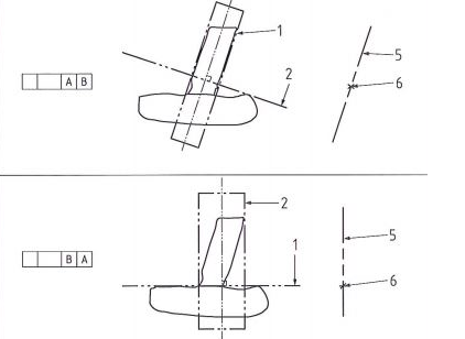
Like wise construct a datum plane from a measured plane relative to another feature (Top image)

Make it possible to re-enumerate feature numbers after program is written/edited.
Your program is finished but some points or features were added and their out of numerical order.
A Re-number feature would put them all in ascending order.
Ability to Assign a Dimension as Attribute
I would like the ability to create an attribute dimension, similar to a "Keyed In" dimension that has a non-numerical value of either "PASS" OR "FAIL" and the ability to pass that result to reports or Excel exports. Currently, all defined dimensions are numerical.
Complete autocalibration routine
Autocalibration Currently does not remeasure failed tips. My suggestion is to implement a feature within the Autocalibration routine that allows it to remeasure the tips that failed the standard deviation. As well as adding a feature within the autocalibration code that allows you to select the calibration sphere when the qualtool has been moved only. This would be used for all autocalibration within that code as well but only selected at the beginning of the program to ensure correct vector and size are used. My expectation if this gets implemented is when i leave on Friday, i can start the autocalibration routine and come back on Monday with no tips that have been outside of the standard deviations.

Gerber Format Support
The Gerber format is a standard ASCII format file structure and uses X, Y, Z and I, J, K information that enables data exchange between CAD (development) and CAM (production). It is primarily used in electronic CAD programs (EDA – Electronic Design Automation) to output layout data for printed circuit boards.
We are frequently confronted with this format and here we have a competitive disadvantage compared to providers who can read this format into their measurement software without further external conversion.
It would therefore be desirable to integrate a corresponding import interface into PC-DMIS.
Min/Max reporting for multi-times hole pattern for size and true positions
Many times we have 25 to 100 x's size and location callouts for pattern of holes. It would be nice to have PC-DMIS be able to output Min/Max GeoTol values without hard coded variable arrays.

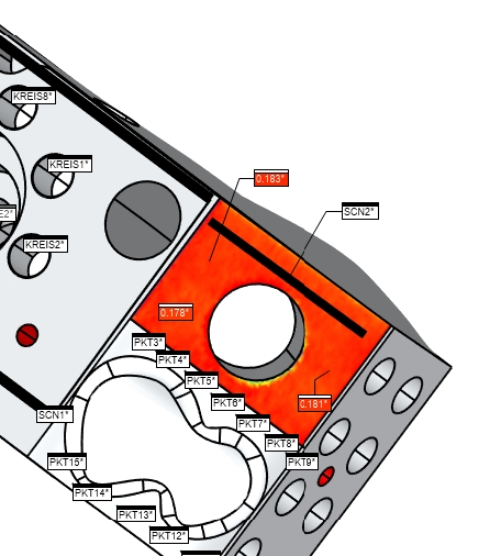
Possibility to scale the size and change the color of type of Annotation Points
As a PC-DMIS User I would like to have the possibility to enlarge the size of Annotation Points created out of Surface colormaps or Pointcloud colormaps. Sometimes it is very hard to read the value inside of Annotation Points, because they are just too small. Sometimes it is hard to read because you do not have a nice contrast between the Type and the background color. In this case it would be nice if I could change the color of the type.
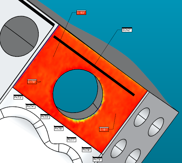
While in Graphic Window the Annotations are good to read, it may be more difficult in Reports, etc.

خدمة دعم العملاء من خلال UserEcho