Hexagon Measurement SystemsNo matter what Hexagon measurement equipment or software you use, we want to hear your ideas and suggestions on how we can improve.
Thanks for your assistance in helping us shape the future. |
|

 Change the toolbar/user configuration files to something readable
Like title.
I would really like to have the toolbar/user configuration files (toolbar.dat, gbarstate.dat, et al.) to something user readable.
Like XML or JSON. When we "move" the old configuration files between versions/upgrades sometimes they end up with duplicate menu items, sometimes missing a menu item...
Today, there isn't a possibility for the user to add/edit the .dat files. This is possible with XML/JSON so the user can "see" if there is a menu item missing/duplicate. The only thing left to do is to delete the files and start over with setting up the GUI in PC-DMIS, which I find quite cumbersome.

 Input comment text size setting, especially when using full screen input comments
I'm currently developing Pc-Dmis programs to be used in production. We typically have operators that run parts on up to 4 cmms each - they're performing setup (no manual measurements), loading parts, following prompts and printing reports only. We utilize bar code / 2d matrix scanners, and when the operators have to enter data into an input comment either manually or with a scanner they cannot easily see the text that has been entered. We use full screen input boxes for user input. I do have some programs that have forms, but I am currently the only programmer at our facility that knows how to create them. Would it be possible to add a text size control (full formatting would be awesome, just like on the forum I'm using now) to input/comment dialog boxes?

 Point density via count vs per mm/in
The ability to simply plug in the amount of points i want for a strategy vs amount of pts/mm would be useful as to not plug in a number that bogs the software into eternity.

 Slot Point Distribution
It would be good to be able to measure hits along the flats of a round-ended slot, instead of being restricted to the radii on the ends of the slot.

 Quick Features - path line graphics
When using Quick Features, Path lines do not display direction, start/end points for Cylinders. Using Auto Features (Cylinders in this case) does. This is a reason for me not to use Quick Features currently but, if these were shown graphically, just like they do for Auto Features, I would be more inclined to use them. (Quick Feature - Cylinder - TOP, Auto Cylinder - BOTTOM)


 Python automated Properties/Criteria
I am currently able to automate the majority of our process. However, I am unable to write anything to the properties or criteria. When I check the recorder it says "Toggle Criteria Reporting - cannot translate". When I try to program it anyway it says its read only. We use it to measure the same shape over and over and it would be much easier and less time consuming to be able to modify the criteria and properties automatically.

 Blade Reporting / Analysis in Pointcloud Section View
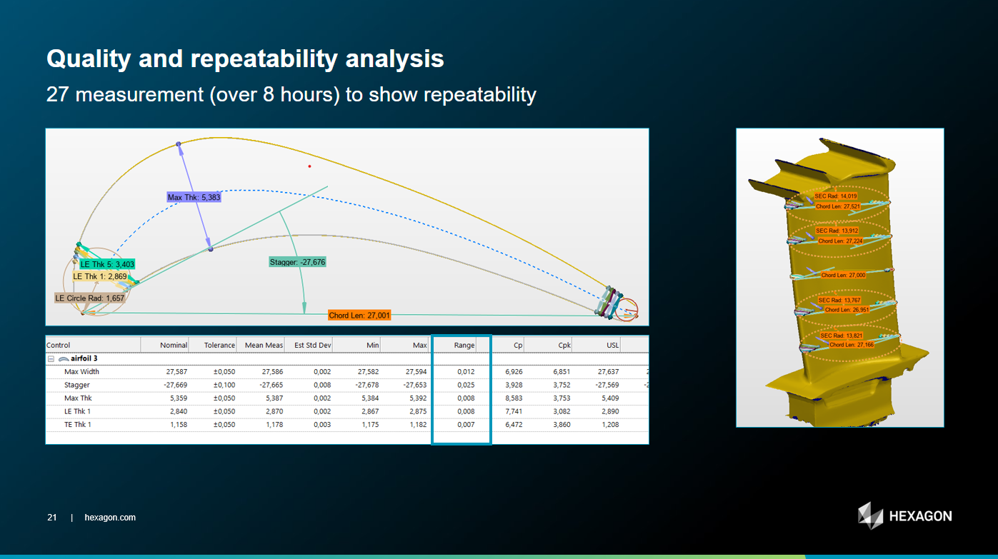
Like Polyworks, have the ability to measure classic Blade Geometry within PC-DMIS COP Sections. Make this functionality native to PC-DMIS CAD++ and not require the use of BLADE module.
Slide image taken from SLS-PW plugin where Max Width, Stagger, Max Thickness, Chord Length, LE & TE Thk are all available.
There is huge business in the UK alone for Blade inspection using Laser sensors on CMM and on Portable Arms.


 BUG: Sometimes the Pop-ups appear in the wrong position (Auto vector Point window)
Hello,
When using multiple monitors, the Auto Vector point window that opens for example disappears (appears in the wrong position somewhere) and is not visible on any of the monitors.
The only problem with this is that although I can close it if I immediately ESC it, d if I click somewhere in the model I am unable to close the Auto Vector window and so I cannot exit the program unless I close it in task manager by ending a task.
I think this might be a bug cause I am experiencing it in 2024.1 and also in 2024.2. It is solved if I reset the user in settings editor, but after a while it comes up again.
It would be great if the windows that open would only appear on valid monitors so if the problem could be solved.
Please register it in the bugs section. Thank you!

 Add Length of Cylinder to the Measurement Strategy Editor and Quick Features Widget
I want to be able to set the length in the Measurement Strategy Editor as well as in the Quick Feature Widget. If the length was included when copying parameters, that would also be helpful. It just seems like cylinder length has been disregarded. We use a lot of cylinders for our hole locations, and sorry to say but the void detection still makes the probe go down too far and it rubs the bottom face. Our threads also do not go the full length of the drilled hole depth, so void detection just doesn't work too well for these features.
Kundesupport af UserEcho


