Hexagon Measurement SystemsNo matter what Hexagon measurement equipment or software you use, we want to hear your ideas and suggestions on how we can improve.
Thanks for your assistance in helping us shape the future. |
|


 Error messages should begin with a distinct identifying alpha-numeric code to provide a simpler means of referencing them. Otherwise, some errors messages have similar text and can be confused.
Error messages should begin with a distinct identifying alpha-numeric code to provide a simpler means of referencing them. Otherwise, some errors messages have similar text and can be confused.

I would like to see the Live Image view so I can use INSPECT on a vision machine, and use the view to do the manual alignment features
At the moment, INSPECT is not very useful for Vision machines, as without seeing the camera view, then the manual alignment features are impossible to position.

Vision - I would like a switch to save ALL images captured by the camera during a program run
In PCDMIS-Vision I would like a switch on/off setting to generate all images captured by the camera during a program run including the display of the measured points. This raw vision data would be extremely useful for root cause analysis.
It would be similar to the existing Diagnostics tool but available in run mode and not requiring to be turned on for each feature. Vision images tell the story of the measurement and are invaluable for troubleshooting and to support cross-sites communication.

Separate PCDMIS installation and license requirement. This is not suitable for enterprise roll-out. License details could be a requirement at runtime.
Current installation mechanism requires local login to PC.
This is time consuming and prevents parallel deployment.
Silent installation is documented... but still requires license and local login ?

A possibility to Add "Tolerances" to colors (RGB) like in Hexagon VISI or maybe in a simpler way
We work more and more with colors and PMI`s to reduce drawings to a minimum.
At the moment we are at the point, that we can handle RGB colors in our CAD, in the CAM and in the Viewer.
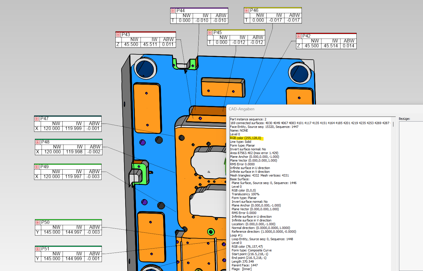
But in our quality department is it not possbile to work with colors in a fast way, because PC-DMIS shows only RGB codes of the Surfaces (Information Surface)
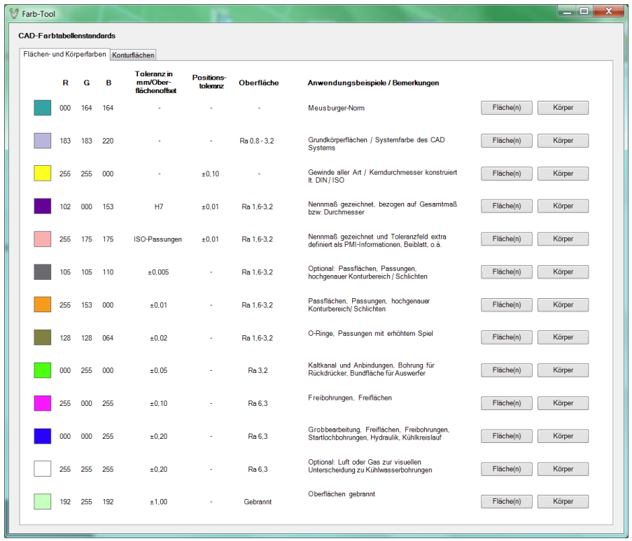
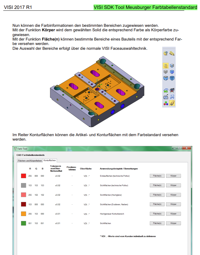
We would wish a to have a possibility to see a tolerance for every RGB color like in Hexagon VISI.
In our business field all companys work already with the similar color code. (Meusburger, VISI, Hasco, VDWF, ....)
Than you don`t need so much time to add PMI`s, because the colors are so much faster and you understand in few seconds the parts and what you have to measure.
Example how you can at the moment see the color in PC-DMIS, but no Tolerance:
This is how you can see it in Hexagon Visi:

Fixture Builder turn off on snapshot when not showing in graphic display window

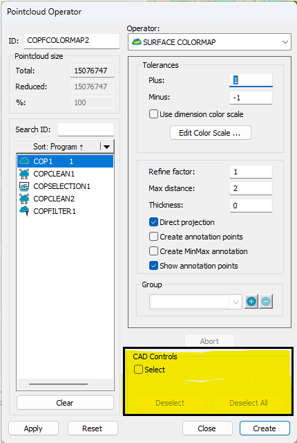
Select funktion
Hi
In recent years, there have been more and more customers manufacturing plates for hydrogen fuel cells or heat exchanger with have many small CAD surfaces (thousands of surfaces). If you want to mark a certain area, you need to zoom in and mark from different angles to cover everything. This takes an enormous amount of time!!!
So I would like to have more options when selecting CAD surfaces. Like, select all, select all in my selection (through/not through/visible only and so on.

Add mark used and global used as parameter set options for Auto Calibrate
Add Mark used and Global used as parameter set options for Auto Calibrate.
Doing this could eliminate the possibility of forgetting to update the Parameter set when the tips used in a measurement routine is updated.
Path Lines Shortcut Key
Function of ALT+P, or another shortcut key, to turn path lines on for highlighted code instead of all instead of having to right click to select

Transform the CAD
Add more tools to easy manipulate the CAD; Sometimes I get the Model with crazy angles, and it is too complicate to transform it
Kundesupport af UserEcho
