Hexagon Measurement SystemsNo matter what Hexagon measurement equipment or software you use, we want to hear your ideas and suggestions on how we can improve.
Thanks for your assistance in helping us shape the future. |
|


 Vision Auto Circle - Start/End position enhancment
Currently, if i'm running percentage based vision circles, I have to guess and check between settings to align gears to teeth while maintaining all of the appropriate settings.
Allow the start and end positions to increment simultaneously by a degree while maintaining settings.
Vision Circles - Percentage improvement
Currently vision segments are restricted to manual segmenting or a generic 10% percent based increment.
Problem - Gear circles often have in excess of 20 teeth and percentages do not line up with arc length of given teeth.
Solution allow percentages in increments of 1%
Variable focus - Vision / Focus Plane
It would be nice to support a quick focus where I can set an intial amount of pre-focus at a lower mag then fine-tune the focus in high-mag - in one feature. Similar to re-measure of a circle.
It would also be nice to have a quick focus feature incorporated into an auto plane where either the first point, three points, or all points have that ability. Rather than multiple alignments, several times.


Add a key in the quick Measurement Strategy Widget where you can difine samble hits .
Add a key in the quick Measurement Strategy Widget where you can difine samble hits ,for now it can't change the sample hits in PC-DMIS R2 with just 0 spacer. Or allow the programer change the hits position manually with the intuitive path line displayed.

Distance evaluation
Hi,
Maybe a bug or removed from program, but earlier it was worked.
It was a good trick, if we did'nt want to change the workplane to evaluation a point to point distance related to third element. Since 2019R2 is not worked.
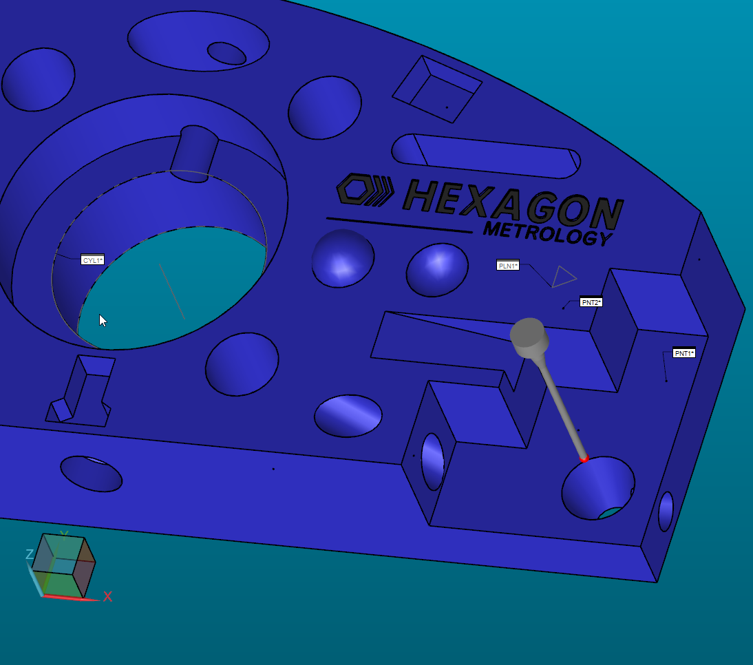
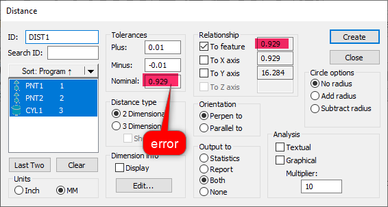
Now If the third element Cylinder,Cone or 3D line(axis) it is not working:
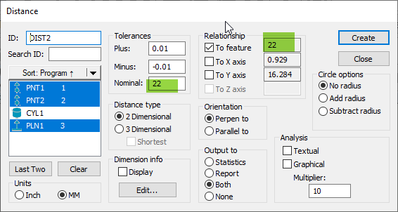
If the third element plane working:
Could we kindly ask to repair this evaluation (ASAP because some of program use this method)
Thanks in advance!
The sample:
PNT1 =FEAT/CONTACT/VECTOR POINT/DEFAULT,CARTESIAN
THEO/<233.319,38.742,-22>,<0,0,1>
ACTL/<233.319,38.742,-22>,<0,0,1>
TARG/<233.319,38.742,-22>,<0,0,1>
SHOW FEATURE PARAMETERS=YES
SURFACE=THICKNESS_NONE,0
MEASURE MODE=NOMINALS
RMEAS=NONE,NONE,NONE
AUTO WRIST=NO
GRAPHICAL ANALYSIS=NO
FEATURE LOCATOR=NO,NO,""
SHOW CONTACT PARAMETERS=YES
AVOIDANCE MOVE=NO,DISTANCE=10
SHOW HITS=NO
PNT2 =FEAT/CONTACT/VECTOR POINT/DEFAULT,CARTESIAN
THEO/<217.035,39.671,0>,<0,0,1>
ACTL/<217.035,39.671,0>,<0,0,1>
TARG/<217.035,39.671,0>,<0,0,1>
SHOW FEATURE PARAMETERS=YES
SURFACE=THICKNESS_NONE,0
MEASURE MODE=NOMINALS
RMEAS=NONE,NONE,NONE
AUTO WRIST=NO
GRAPHICAL ANALYSIS=NO
FEATURE LOCATOR=NO,NO,""
SHOW CONTACT PARAMETERS=YES
AVOIDANCE MOVE=NO,DISTANCE=10
SHOW HITS=NO
CYL1 =FEAT/CONTACT/CYLINDER/DEFAULT,CARTESIAN,IN,LEAST_SQR
THEO/<124,50,-15>,<0,0,1>,44,20
ACTL/<124,50,-15>,<0,0,1>,44,20
TARG/<124,50,-15>,<0,0,1>
START ANG=0,END ANG=360
ANGLE VEC=<1,0,0>
DIRECTION=CCW
SHOW FEATURE PARAMETERS=YES
VOID DETECTION=NO
REMEASURE=NO,USE THEO=NO
SURFACE=THICKNESS_NONE,0
MEASURE MODE=NOMINALS
RMEAS=NONE,NONE,NONE
AUTO WRIST=NO
GRAPHICAL ANALYSIS=NO
FEATURE LOCATOR=NO,NO,""
SHOW CONTACT PARAMETERS=YES
NUMHITS=3,NUMLEVELS=3,DEPTH=0,END OFFSET=0,PITCH=0
SAMPLE METHOD=SAMPLE_HITS
SAMPLE HITS=0,SPACER=0
AVOIDANCE MOVE=BOTH,DISTANCE=10
FIND HOLE=DISABLED,ONERROR=NO,READ POS=NO
SHOW HITS=NO
COMMENT/REPT,
NOT OK- NOT working :-( Old version it was worked.
We use this lot of time because not neccesery to change the workplane
DIM DIST1= 2D DISTANCE FROM POINT PNT1 TO POINT PNT2 PERP TO CYLINDER CYL1,NO_RADIUS UNITS=MM,$
GRAPH=OFF TEXT=OFF MULT=10.00 OUTPUT=BOTH
AX NOMINAL +TOL -TOL MEAS DEV OUTTOL
M 0.929 0.010 -0.010 0.929 0.000 0.000 ----#----
PLN1 =FEAT/CONTACT/PLANE/DEFAULT,CARTESIAN,OUTLINE,LEAST_SQR
THEO/<214.878,46.819,0>,<0,0,1>
ACTL/<214.878,46.819,0>,<0,0,1>
TARG/<214.878,46.819,0>,<0,0,1>
ANGLE VEC=<1,0,0>,RADIAL
SHOW FEATURE PARAMETERS=YES
VOID DETECTION=NO
SURFACE=THICKNESS_NONE,0
MEASURE MODE=NOMINALS
RMEAS=NONE,NONE,NONE
AUTO WRIST=NO
GRAPHICAL ANALYSIS=NO
FEATURE LOCATOR=NO,NO,""
SHOW CONTACT PARAMETERS=YES
NUMHITS=3,NUMROWS=3
SPACER=0
AVOIDANCE MOVE=BOTH,DISTANCE=10
SHOW HITS=NO
COMMENT/REPT,
OK
DIM DIST2= 2D DISTANCE FROM POINT PNT1 TO POINT PNT2 PERP TO PLANE PLN1,NO_RADIUS UNITS=MM,$
GRAPH=OFF TEXT=OFF MULT=10.00 OUTPUT=BOTH
AX NOMINAL +TOL -TOL MEAS DEV OUTTOL
M 22.000 0.010 -0.010 22.000 0.000 0.000 ----#----

Real Vector direction, including T, I,J,K of an intersection point should be calculated correctly
Up to version 2019, there is no actually vector direction of intersection point. T, I, J,K should be calculated so the point can be more useful when doing comparison. for now T, I, J, K are set at default value.
scan feature (when using scan feature) should also has "relative to" option like point/plan/circle
user can use "relative to" option on scan feature to get reference location before touching off on real feature like point/plan/circle feature. "relative to" option is very useful on point/plan/circle feature. when I dealing with scan, it is very hard to touch correctly because variation on real part. I would love to use "relative to" on scan when it is available.

Alarm after probe change is initiated
Have PC-DMIS prompt what probe is loaded any time there is an alarm after the probe change is initiated. Many time it looses track of what probe it has and crashes into the probe change rack. This happens often if a probe oscillation error occurs after the probe change sequence has started.
خدمة دعم العملاء من خلال UserEcho