Hexagon Measurement SystemsNo matter what Hexagon measurement equipment or software you use, we want to hear your ideas and suggestions on how we can improve.
Thanks for your assistance in helping us shape the future. |
|


 Master routine / Routine sequence
Kindly asking if there would be possible to have several routines that I need to run in specific sequence, and those would be opened in master routine, or on finishing a routine, printing event would happen and a question would appear, if PCDMIS should continue with the next defined routine in row, where another routine would be opened in PCDMIS and executed.
Not like current mini routines.

Quindos Converter
Hello Everyone,
It would be great if it were possible to create a converter for Quindos programmes to PC-Dmis.
I have several clients who would switch software on the spot.

GD&T CAD & OCR Select feature creations should follow any active default MSE we use for QuickFeatures
Say I bring it a CAD model w/ embedded PMI (GD&T) or use the GD&T select from image option, features that are creating ignore any active MSE (default group) that would work with QuickMeasure. This means, one has to edit the auto feature after the fact. Same seems to be the issue if creating auto features using the toolbar and dialog. They do remember what user last did, but they do not follow the MSE when creating new routines. This also means that items like AutoWrist get ignored. Only workaround I can find is to QuickMeasure create the feature first and then Click/use the GD&T callout. If Assuming I have the correct feature type for the association.

Check that all features are reported.
A way to check to see if you reported measurements on all features measured so you don't forget to report on them.

Reopen a completed run without the physical part present
I would like PC-DMIS to support a replayable measurement result package similar in functionality to ZEISS Calypso’s saved measurement data concept.
The purpose is to reopen a completed run without the physical part present, using stored measured points, constructed features, alignments, and run-specific evaluation data.
PC-DMIS already appears to generate interim or backup data between runs, which suggests an existing mechanism that could potentially be extended into a formal run snapshot / replay file.
This would provide major benefits for offline analysis, troubleshooting, reporting, training, reproducibility, and reduced machine occupation.
Ideally the stored package should include:
-
measured hit points / scan points
-
calculated features
-
active alignment and datum state
-
sensor context
-
timestamp / operator metadata
-
optional CAD link reference
The main goal is not full raw machine logging, but a practical, reopenable measurement dataset that allows re-evaluation without remeasuring the physical part.

Add VISI to the supported CAD formats in Replace Component
I would like to see VISI cad file support added to the Replace Component function in CAD Assembly.

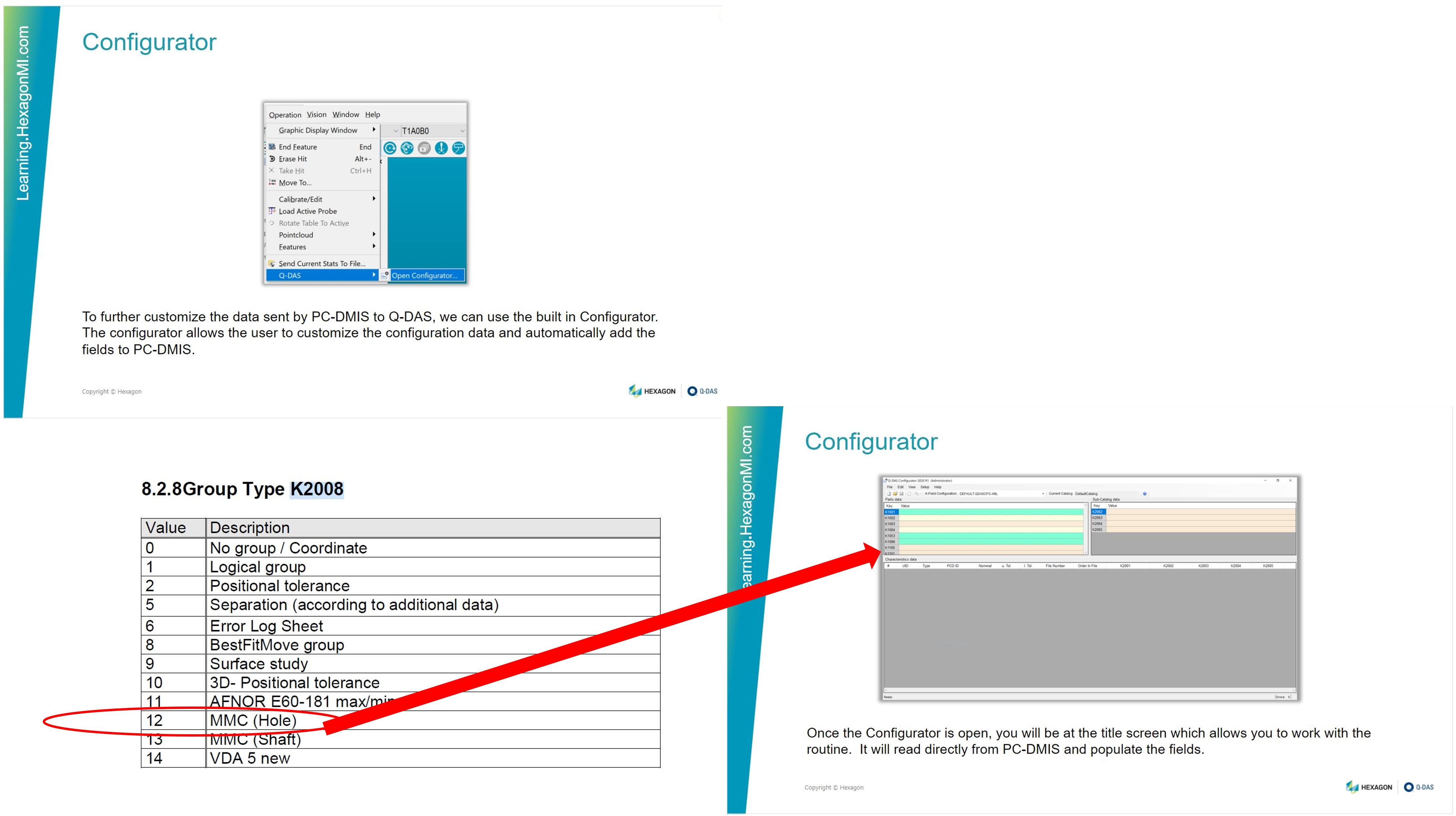
Add a grouping key field, 2008 12 MMC Hole PC-DMIS – Q-DAS built in configurator
Add a grouping key field, 2008 12 MMC Hole PC-DMIS – Q-DAS built in configurator.
Persistent toolbars and buttons across users
I would like a custom toolbar that can appear on every user's toolbar area by default just like the standard ones. It would be incredibly handy to have a toolbar with custom function buttons that everyone has access to. It would also streamline so many other things including setup and work instructions. Currently, to get that functionality, each user would have to configure their toolbar, which isn't practical for shops with multiple users and skill levels. I would love to say in my work instructions: "press the <setup instructions> button in the toolbar" and know they have that button.

Copy ABC paste CBA
In the edit window, I would like to be able to copy a set of elements ordered as A-B-C-D and paste them as D-C-B-A.
Customer support service by UserEcho
