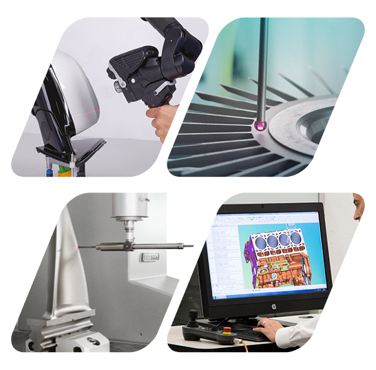
Hexagon Measurement SystemsNo matter what Hexagon measurement equipment or software you use, we want to hear your ideas and suggestions on how we can improve.
Thanks for your assistance in helping us shape the future. |
|

 roughness evaluation from CWS scan on vision machines
Optiv machine equipped with cws 1mm can generate COPs that shall be used to calculate roughness dimensions.
Actually the processing of the COPs is made with an additional external Software.
An implementation of the roughness in pcdmis would make this measurement less complicate and reduce Costs for external Software (Mahr).

 Adaptive circle scan sample hits/remeasure
Would like to take "sample hits" in diameters and then scan with the updated size/location. Sometimes a diameter is allowed to vary drastically but still needs scanned. Maybe something a little more elegant than measuring a 3 point circle and updating from it.

 concentricity and coaxiality - References "A-B"
Why can't I use the "A-B" cover for concentricity and coaxiality?
References are circles and cylinders.

 Searchable features in ClearanceCube Definition Status Tab
I'd like to be able to search for a given feature in the ClearanceCube Definition Status Tab. Scrolling thru a mile long list is not fun. In an ideal world, if the Clearance Cube Definition Status tab was open clicking on a feature label in the graphics window would take you to the feature in the Status tab.

 Transformation help
In version 2020R1, with the transformation window open, an autofeature cannot be selected. This feature was available in previous versions. Being able to open an autofeature assists in finding unknown cad locations for assisting transformations.

 Scan point location
On version 2015.1, with "Show Hits" enabled in the edit window, a point on the scan can be highlighted and with the "move cursor to" command, the individual point hit vector would be identified in the edit window. This feature is not working on version 2017R2, 2019R1 and 2020R1 etc.. Can this feature be reincorporated into newer versions of PCDMIS?

 Calibrate Tips and Probes for Program
Add to the calibrate tips feature to be able to calibrate multiple probes for a program as well.

 end of dimension
end of dimensions missing on a lot of dimensional reporting, this sometimes deletes it's self or isn't there from the get go. can this be added as a default to come up for everything regardless that way it won't be an issue and will be easily seen if it 'goes missing'

 collision avoidance into machine bridge legs before probe rotation during measuring process
Collision avoidance into machine bridge legs before probe rotation during measuring process, Just a collision prompt before the probe rotation is OK, if the CMM Limits is supplied.
Сервис поддержки клиентов работает на платформе UserEcho


