Hexagon Measurement SystemsNo matter what Hexagon measurement equipment or software you use, we want to hear your ideas and suggestions on how we can improve.
Thanks for your assistance in helping us shape the future. |
|


 default to LAST prehit retract values
When measuring in a channel on flexible rings
I need to adjust the prehit retract values to get a good hit to analyze the data.
I do this in the edit window I type
prehit and TAB it auto fills the 2.54 value :(
What would be useful is the
ACTUAL LIVE VALUE at that point in the program so I know to go bigger or smaller than what I currently have.
it may have hit either wall and bounced off ... so it starts a trial and error routine and is time consuming.

profile radius Algorithm In a auto circle feature
When measuring the size of a radius with a small arch angle using auto features usually reports the radius incorrectly, a work around for this is to change the origin to the theatrical arch center then take Polar RAD hits and average the hit with a variable then populate a generic feature with that variable. It would be convenient to have a drop down for this in the advanced measurement options best fit math type, this would save a lot of programming time.

legacy icons

Build a color map of a measured part in comparison with another measured part pattern but not with CAD
It would be great to be able to build a color map of a measured part based on its comparison with another patter-part and no with its CAD.
This option would be very usefull, for example, in the case where we have 2 parts: at first sight both of the parts have the same dimensions because the results of the measurements of both parts with caliper are similar and both parts are on tolerance with the CAD/drawing, but only one of them could be assembled. So, it would have sense that the difference between them must be on the shape, and the mentioned option would be the best chance to be able to see it.

Number idenifying algorithm - Vision support
I inspect a lot of small components with cavity number identifiers. It would help with automation to have an algorithm that works like an OCR and can be used to autofill key-in fields.
Additionally, I've had jobs that define the true position of a Letter.

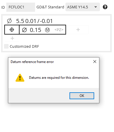
Position to No Datums
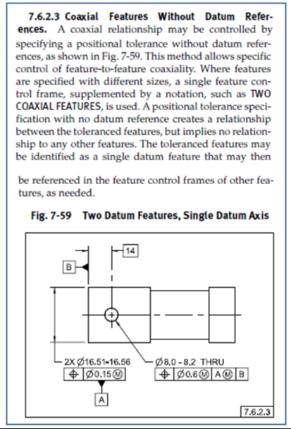
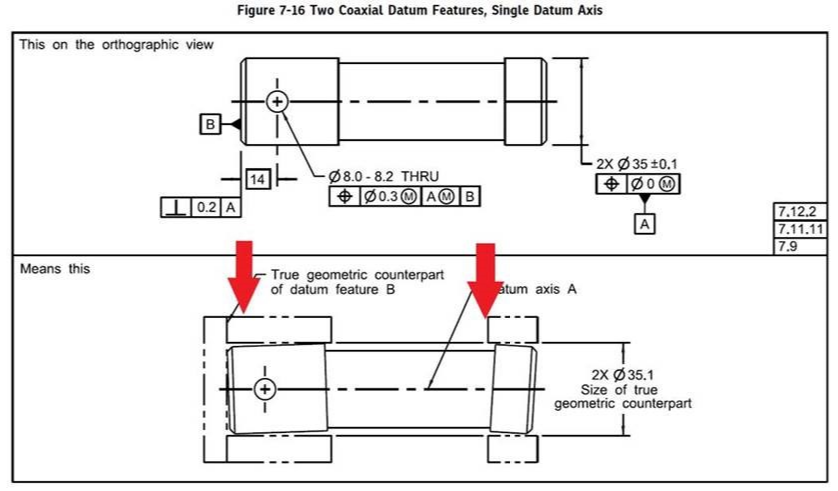
ASME Y14.5-2009 7.6.2.3 Coaxial Features Without Datum References
This is an ability that I would like to see in PC-DMIS Xact-Measure.
If the call out is per the spec then PC-DMIS should abide by the standard.

ÇOKLU DELİK SEÇİMİ
AYNI DELİKTEN FAZLA OLDUĞU ZAMAN TABANA DOKUNUP AYNI TABANDA OLAN DELIKLERI 'SHIFT' E BASARAK SİLİNDİRMİ YADA DELİKMİ OLDUĞUNU SEÇERKEN HATVE (PİTCH) DEĞERİ GİREMİYORUM BUNUN EKLENMESİ GEREK..

excel macro reports from .XLSM to .XLSX or bring back .xlsm.
As it stands now. .xlsm (macro) is not an option and .XLSX is the new version but, does not work correctly.
.xlsm is 1997 version. I have worked with these sheet forever and the new PCDMIS wizard does not even
work anymore.
Servicio de atención al cliente por UserEcho
