Hexagon Measurement SystemsNo matter what Hexagon measurement equipment or software you use, we want to hear your ideas and suggestions on how we can improve.
Thanks for your assistance in helping us shape the future. |
|


 Command Mode - Dynamic Zoom with <CTRL> + Mouse Scroll
Command mode has visual challenges. Small text (fonts), while difficult to see, is good for seeing the whole program - especially features with long widths across. Large text (fonts) is good for detail and visibility, but the field of view gets cropped.
Changing fonts by pressing F6, then clicking "Edit Window", and THEN selecting the font size, is archaic.
A huge improvement would be if Command Mode allowed Dynamic Zoom (or Font Scaling) using <CTRL> + Mouse Scroll. Examples of this are available in Visual Studio's editor, MS Word, and Notepad++.
Note the attached MP4 of Visual Studio scrolling in and out of code details.

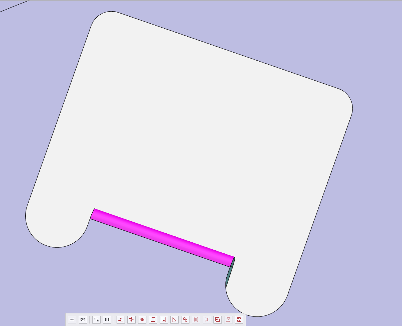
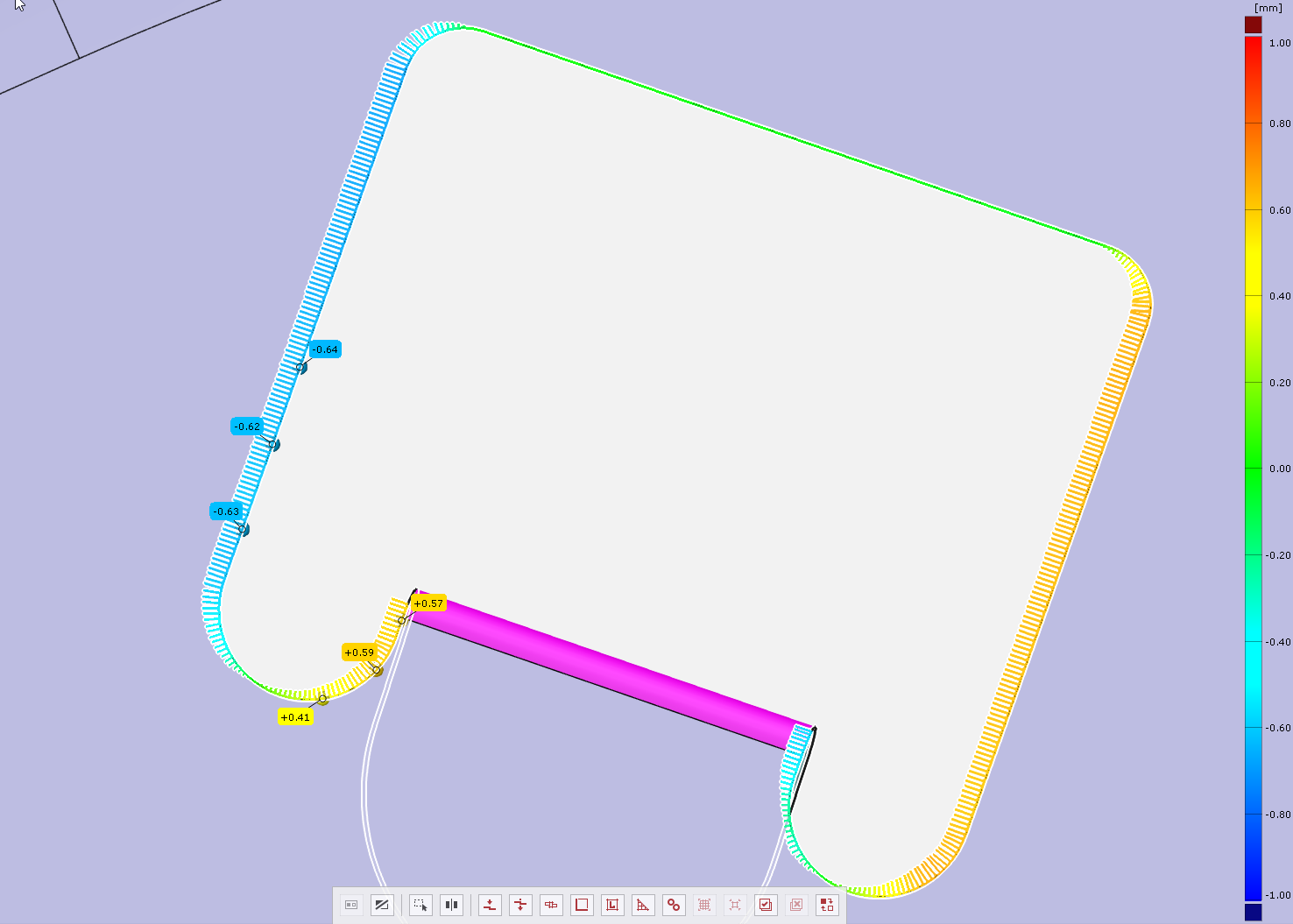
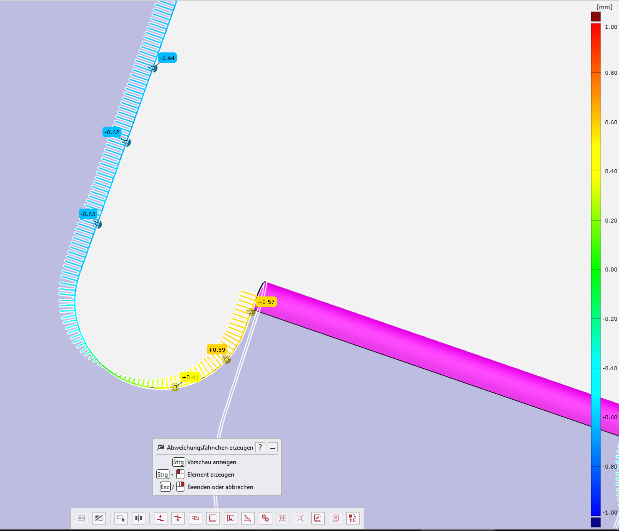
Calculation and representation of a trimline from the point cloud (Sheetmetal).
2019-05-28 12_21_34-7337543_AD_LI_RADHAUS_A....png
2019-05-28 12_21_22-7337543_AD_LI_RADHAUS_A....png
2019-05-28 12_20_14-.png
In other Measuring Software you can show the trimline of sheet metal work pieces, like Pcdmis do it in cross section and line profile. But it is not possible to use for trimlines, because of the high deviation or the contour of the trimline. It would be nice, if it worked like the cross section.

Field Editor
Command Mode
Summary ModeDmis Mode
New Mode - Field Editor Mode (or Filter mode?)
Basically it's command mode - except you can filter what it shows:
Example - Avoidance moves only (probe)
Example - light settings only (vision)
Example - Measure Now/Remeasure
Example - Relative Too
It would also be nice, that if you are in this mode PCDMIS would see that you are not changing anything relevant to an alignment - and thus the prompts would act accordingly.

Auto square slot with radius corners
An Auto Square slot that also checks corner radius. Reports center location, length, width, and corner radius.

Different hole diameters with composite pattern
When selecting holes with a composite pattern true position requirement the tolerancing window automatically filters the selectable holes to only list holes of identical sizes. Previous versions of PC-DMIS would let us select holes of any diameter from the tolerancing window to include in a pattern requirement.
Output Form Deviations EXCELFORMREPORT
EXCELFORMREPORT does not allow the individual points of form tolerances to be output, only the min/max and measured values. For customers with point maps it would be nice to be able to see all of the form deviations.
Allow full path to be set in EXCELFORMREPORT
Currently EXCELFORMREPORT does not allow you to set the whole path, only the directory where the files go. It would be convenient to set the full path, similar to how the print command works.
We read in the full path of the report name from a file because we often have reports that need to relate to each other so the initial part of the name needs to be the same

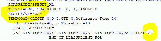
TempComp with ASSIGN
Is it possible to replace the measured value of the workpiece with a variable in the TempComp command?

Add "Show Report" checkbox to the new Excel Form Report
I'd like to see the "Show Report" checkbox added to the new Excel Form Report to give users the same report viewing option they have in Report Print Options.
Calibrate while programming
Fairly often I am programming and could also be calibrating tips. It would be neat if this was optimized to perform this way.
Sometimes I'll save my online program, create a dummy program and calibrate tips and move to my online program offline and programming depending on the amount of tips being calibrated. Even this sometimes causes some difficulties.
خدمة دعم العملاء من خلال UserEcho
