Hexagon Measurement SystemsNo matter what Hexagon measurement equipment or software you use, we want to hear your ideas and suggestions on how we can improve.
Thanks for your assistance in helping us shape the future. |
|


 Add a native way to constract a contact circle from 2 different scans
PC-DMIS allows to construct a contact circle from 1 scan (it's called minimum scan in the circle dialog).
The problem is it works only with one input feature.
PC-DMIS should get the ability to also calculate contact circles from multiple scans and also from constructed filtered features (so the contact circle is more repeatable).
See the following links to the User Forum:
- https://www.pcdmisforum.com/forum/pc-dmis-enterprise-metrology-software/pc-dmis-for-cmms/534132-need-help-with-the-function-scan-minimum-when-creating-a-circle
- https://www.pcdmisforum.com/forum/pc-dmis-enterprise-metrology-software/pc-dmis-code-samples/534188-combine-points-from-two-filtered-scans-into-one-container-scan#post534188

Combined GD&T callouts
Add the option to combine different GD&T into one callout, which would match the drawing. E.g. Size/Circularity/Perpendicularity in one callout.

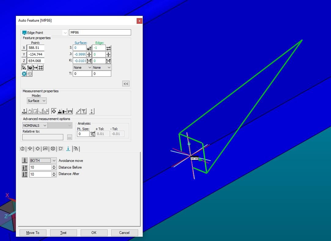
extract point from edge point
When I create an edge point, there should be an option so I can extract the points with the appropriate move
Add math selector of tolerance zone for profile with datum
Add a math selector of the tolerance zone when evaluating a profile with a datum (line or surface)
At the moment it automatically uses the "Default" math. It should be possible to use the "LSQ" math.
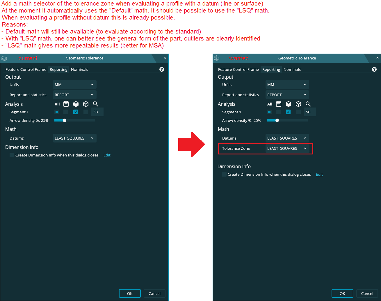
When evaluating a profile without datum this is already possible.
Reasons:
- Default math will still be available (to evaluate according to the standard)
- With "LSQ" math, one can better see the general form of the part, outliers are clearly identified
- "LSQ" math gives more repeatable results (better for MSA)
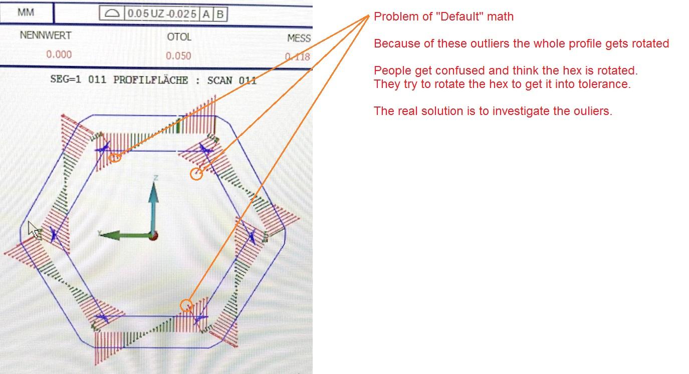
I understand that the "Default" math is the one we should use to measure according to the standard
but it can be difficult to understand the result it delivers. "LSQ" math gives easier to understand results witch is crucial to adjust the machine.
See this example:

Make Prehit and Retract together as one adjustable setting.
Make Prehit and Retract together as one adjustable setting. Why do we need to have 2 separate settings?

Scans and Cad model match problem
After we end up our offline programs. We saw that after re runing on offline scans turns in to the Master (they programmed at findnoms). And stays away from the cad model. Is there any way to stop this change?
Solutions:
If you operate the collision test it will relocate on cad model.
At measured programs scan results could not match the cad model. Because of that we can not analyse our part results. Is there any solution for that too? Capture.PNG

Auto Dimension Button
I would like to have a button to turn on or off the Auto Dimension feature. The current method is not an ideal workflow. It is either always on or always off. If I could turn it off/on from an icon or from the MSE, then that would be extraordinary.
Improve changing the datums in GD&T command
When changing a datum of a GD&T command from the command-view the subsequent datums get deleted.
This should get improved. So I can change the middle datum without the last being removed.
Example:
I have the datum system |A|B|C| I want to change it to |A|M|C|
The second I change the |B| to an |M| in the command-view the |C| gets deleted and I only get a |A|M|
Improve renaming of Datums
When an existing Datum gets renamed the GD&T commands don't get updated and still display the old letter.
This should get fixed and handled like the renaming of other features (like circles).
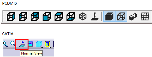
looking perpendicular at the solid model
Hi guys,
There should be a button in Graphic View to be able to look at the part on angled surfaces perpendicular to their surfaces.It's like the Normal View button on Catia.
See below picture..
Customer support service by UserEcho
