Hexagon Measurement SystemsNo matter what Hexagon measurement equipment or software you use, we want to hear your ideas and suggestions on how we can improve.
Thanks for your assistance in helping us shape the future. |
|

 Add formulas to all Text boxes (with Assignments)
Make X/Y/Z/I/J/K/Dia/etc have the ability to accept and recognize formulas (and variables/Assignments). After entering the formula it should stay active/visible for easy editing in the future.

Change the generic feature creation to include a drop down selection of previously measured features
Change the generic feature creation to include a drop down selection of previously measured features such that you could select PLN1.TX - Cir2.TY - Line3.TZ and PLN1.X - CIR2.Y - Line3.Z to populate the new generic feature as you create it.

Error messages should begin with a distinct identifying alpha-numeric code to provide a simpler means of referencing them. Otherwise, some errors messages have similar text and can be confused.
Error messages should begin with a distinct identifying alpha-numeric code to provide a simpler means of referencing them. Otherwise, some errors messages have similar text and can be confused.

I would like to see the Live Image view so I can use INSPECT on a vision machine, and use the view to do the manual alignment features
At the moment, INSPECT is not very useful for Vision machines, as without seeing the camera view, then the manual alignment features are impossible to position.
Add the axis and workpiece temperatures to the "probe reading" window
It is often useful to know the temperatures of the axes and the workpiece in real time without having to call up the thermal compensation command.
PC-DMIS does not have a window that displays these temperatures in real time.

Remember custom colors across routines
When you add a custom color (for example CAD model color), that custom color doesn't show up in other routines. If you want consistency across routines, you need to keep a separate list of any custom colors you use, and manually add them when needed. I'd love it if custom colors could be remembered globally.
Allow combination of cylinder + width or circle + width for common datum in PC-DMIS
I want the combination of cylinder + width and circle + width to be allowed to be used as common datum. Currently it is not. According to ISO 5459 rules, this would be equal to be using the [DF]-modifier when the datums are separated. While using DF is fine, allowing the common datum combination removes the risk of unnecessary questions or discussions on how the final report should look, making the report mirror the requirement in the drawings.

Warning if your tip combination is out of spec
I would like PC-Dmis to warn when defining a tip that is too heavy and also if it is outside limits of what the probe can handle.
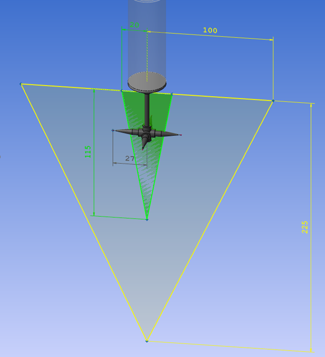
Below a tip that is outside the specific volume for an HP-S-X1S. But inside an HP-S-X1H
The weight of the tip is 15.4 grams, so it can handle the weight of both probes but not the size and position of an HP-S-X1S.
HP-S-X1S: max 20g
HP-S-X1H: max 33g
Automatic settings for UPR and cutoff wavelength
I absolutely love the automatic scanning parameters based on size/position/form in PC-DMIS. It's a set it, forget it thing for me. However, when it comes to the gaussian filter settings, things can get complicated. The general rule is that you need at least 7 points per undulation/wavelength. A lot of the literature talks about a given UPR/wavelength, and then changing the number of points scanned accordingly. However, the point density is automatically determined based on size/position/form, and you have little influence on the scanning path. The number of points therefore is set, and you need to change the filter settings accordingly. I use a little Excel sheet where I can enter the point density per millimeter that PC-DMIS has cooked up for me (you also need to enter the diameter for round features). The sheet will spit out the filter settings based on 8 points per undulation/wavelength (1 more than the minimum). This has worked very well for me, but it's a lot of work to set up for each feature. It's also easy to forget. Especially when scanning large diameters this can cause problems. Filtering a 500mm diameter with a point density of 6 with only 15 UPR is not ideal...
In summary: I'd love to see some kind of optional setting where you can change the filter strength based on the points per undulation/wavelength, rather than some absolute value that doesn't tell you anything without knowing the scanning density and diameter of the feature. 7 would be the minimum setting, to help prevent novices from filtering wrong. People like myself could set it to 8 and make it default. If you need a more aggressive filter, just increase the points per undulations/wavelength. Or just enter the UPR or wavelength manually, if that's your jam.

Enable viewing of summary mode and command mode at the same time.
It would make it easier to follow the program and edit directly in the code at the same time
Customer support service by UserEcho