Hexagon Measurement SystemsNo matter what Hexagon measurement equipment or software you use, we want to hear your ideas and suggestions on how we can improve.
Thanks for your assistance in helping us shape the future. |
|


 New point construction method: "high point"
Finding the "high point" of a feature or scan is a very common measurement task.
In pc-dmis, this is a complex task, that requires an understanding of array indexing, and significant manual entry into a generic feature. It is prone to error, is very time consuming, and for users never exposed to a programming language it's a complete non-starter.
A simple, interface-based point construction method could be added to address these issues. The new method should be based on the DMIS method "CONST/EXTREM". It is very complete, and since pc-dmis imports DMIS code - it only makes sense to have a 1 to1 mapping of the DMIS definition.

Add a length and width spacer option for auto planes
Currently PC-DMIS has a square spacer that can be set for auto planes. It would be nice if we could specify the length and width of the spacer

Basic Dimension option
How about a Basic Dimension option, in the Location Tool Box. That way the basic dimensions don't need to have tolerances.

Angular Length Reporting
 Maybe there is an easy way to report it ;if we have either a check box on the location (angle between) dialog window like "from formula" or an easier assignment set will be great.
Here is the code in order to report it :
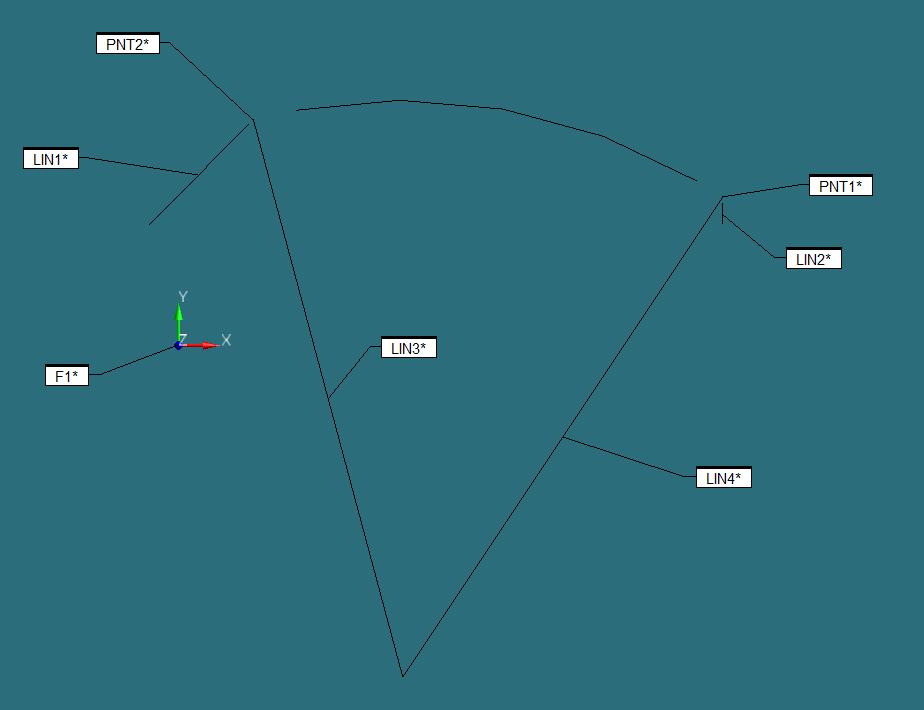
CIR1 =FEAT/CIRCLE,CARTESIAN,OUT,LEAST_SQR
THEO/<98.516,-145.613,-2.547>,<0,0,1>,506.5,0
ACTL/<98.516,-145.613,-2.547>,<0,0,1>,506.5,0
MEAS/CIRCLE,4,ZPLUS
HIT/BASIC,NORMAL,<51.696,103.272,-2.55>,<-0.1848771,0.9827616,0>,<51.696,103.272,-2.55>,USE THEO=YES HIT/BASIC,NORMAL,<99.287,107.636,-1.309>,<0.0030416,0.9999954,0>,<99.287,107.636,-1.309>,USE THEO=YES
HIT/BASIC,NORMAL,<166.819,98.253,-3.669>,<0.2697032,0.9629435,0>,<166.819,98.253,-3.669>,USE THEO=YES
HIT/BASIC,NORMAL,<227.698,72.212,-2.661>,<0.5100969,0.8601169,0>,<227.698,72.212,-2.661>,USE THEO=YES
ENDMEAS/
LIN1 =FEAT/LINE,CARTESIAN,UNBOUNDED
THEO/<31.03,97.103,-1.56>,<-0.7071068,-0.7071068,0>
ACTL/<31.03,97.103,-1.56>,<-0.7071068,-0.7071068,0>
MEAS/LINE,2,ZPLUS
HIT/BASIC,NORMAL,<31.03,97.103,1.086>,<-0.7071068,0.7071068,0>,<31.03,97.103,1.086>,USE THEO=YES
HIT/BASIC,NORMAL,<-13.352,52.72,-4.207>,<-0.7071068,0.7071068,0>,<-13.352,52.72,-4.207>,USE THEO=YES
ENDMEAS/
LIN2 =FEAT/LINE,CARTESIAN,UNBOUNDED
THEO/<239,62.251,-5.264>,<0,-1,0>
ACTL/<239,62.251,-5.264>,<0,-1,0>
MEAS/LINE,2,ZPLUS
HIT/BASIC,NORMAL,<239,62.251,-5.016>,<1,0,0>,<239,62.251,-5.016>,USE THEO=YES
HIT/BASIC,NORMAL,<239,53.115,-5.512>,<1,0,0>,<239,53.115,-5.512>,USE THEO=YES
ENDMEAS/
PNT1 =FEAT/POINT,CARTESIAN,NO
THEO/<239,65.1,-5.264>,<0,-1,0>
ACTL/<239,65.1,-5.264>,<0,-1,0>
CONSTR/POINT,PIERCE,CIR1,LIN2
PNT2 =FEAT/POINT,CARTESIAN,NO
THEO/<32.922,98.995,-1.56>,<-0.7071068,-0.7071068,0>
ACTL/<32.922,98.995,-1.56>,<-0.7071068,-0.7071068,0>
CONSTR/POINT,PIERCE,CIR1,LIN1
LIN3 =FEAT/LINE,CARTESIAN,UNBOUNDED,NO
THEO/<98.516,-145.613,-2.547>,<-0.259008,0.9658673,0.0038973>
ACTL/<98.516,-145.613,-2.547>,<-0.259008,0.9658673,0.0038973>
CONSTR/LINE,BF,3D,CIR1,PNT2,,
OUTLIER_REMOVAL/OFF,3
FILTER/OFF,WAVELENGTH=0
LIN4 =FEAT/LINE,CARTESIAN,UNBOUNDED,NO
THEO/<98.516,-145.613,-2.547>,<0.5546916,0.8319869,-0.0107257>
ACTL/<98.516,-145.613,-2.547>,<0.5546916,0.8319869,-0.0107257>
CONSTR/LINE,BF,3D,CIR1,PNT1,,
OUTLIER_REMOVAL/OFF,3
FILTER/OFF,WAVELENGTH=0
DIM ANGL1= 2D ANGLE FROM LINE LIN4 TO LINE LIN3 ,$
GRAPH=OFF TEXT=OFF MULT=10.00 OUTPUT=BOTH
AX MEAS NOMINAL +TOL -TOL DEV OUTTOL
A 48.703 48.703 0.010 0.010 0.000 0.000 ----#----
ASSIGN/V1=((2*3.14*CIR1.R.MEAS)/360)*ANGL1.A.MEAS
F1 =GENERIC/NONE,DEPENDENT,CARTESIAN,OUT,$
NOM/XYZ,<0,0,0>,$ MEAS/XYZ,<0,0,0>,$
NOM/IJK,<0,0,1>,$
MEAS/IJK,<0,0,1>,$
RADIUS/0,0,$
ANGLE/215.5,V1,$
DISTANCE/0,0
DIM LOC1= LOCATION OF PLANE F1 UNITS=MM ,$
GRAPH=OFF TEXT=OFF MULT=10.00 OUTPUT=BOTH HALF ANGLE=NO
AX MEAS NOMINAL +TOL -TOL DEV OUTTOL
A 215.160 215.500 0.500 0.500 -0.340 0.000 -#-------
END OF DIMENSION LOC1

Allow Max & Min Index of Polar Radius from a scanned feature
When finding a high point of a linear feature it's possible to use the Maxindex assignment relative to a specific axis. For example "maxindex(scan.x)". This will return the max value in X for that scan.
When scanning radial features and finding a max Polar Radius, one would expect to use "maxindex(scan.PR)" to return the max value for PR in that scan. Thus giving a high point of a radius for example.
This command doesn't work with polar radius.

Ability to choose report method from Cartesian to radial or spherical on geometrical results.
We have many drawings that have surface profiles, the dimensions may apply to flat, angles, curved, radial and spherical surfaces which have BASIC controls that when reported, do not match the drawing at all, this is due to the fact that when choosing to report a surface profile, the data shown is in Cartesian and no choice for radial or spherical to report. When programming to create a new coordinate that sets the origin to a location and be able to measure radial points or surfaces, the output data needs to have the relationship to match the drawing call out, this helps with making decision on mold making, machining and or part configuration. Customers also have no correlation of results to drawing, X,Y,Z does not corollate if features are radial or spherical when looking at the surface profile point data to evaluate.

Program Single Block Mode
It would be nice to see an addition of a 'single block' mode, similarly to CNC machines where you can step through each line/block of code one at a time. This would be good for proving out program or certain sections of programs. This would be better than having to CTRL+E each line to make sure things dont crash.
Adding a single block toggle to the execution popup window while executing would have the user click the play button/green button on the jogbox to advance each block.

Add UPR as smart parameter in the measurement strategy editor
As more and more customers are asking us to scan (with a probe) all features, they also got their standards for using the filters in scanning. In those standards, they also ask for a specific UPR which relates to the current diameter. For example, Ø8 and smaller require a UPR setting of 15. Ø8-Ø25 require UPR 50 etc.
I'd like to add this as a smart parameter in the Measurement Strategy Editor to make sure we also use the correct settings.
AUTO PLANE RINGS
I would like to see an option where we can adjust the distance between multiple rings when checking a radial auto plane. We of course have the option to adjust the size of the rings but, to my knowledge, don't have the option to adjust the distance between.

Comment Box Update!
I think the Comment box could use some help. I've been using PCDMIS since the 2014 version and its basically untouched in 10 years. As an offline programmer, the comments are sometimes the only way I can communicate to the inspection operators.
I have seen some people on here asking for Font Types and Colors, and i think that's a really great idea!
I would also like to see more ALT codes translated correctly to the comment box, or maybe add more than the four symbols at the bottom of the Comment Text Box. GD&T uses so many different symbols to communicate there should be a library to choose from when typing out or operator comments.
Even as I type this out, I'm looking at the options i have to edit my text and I would love to see something similar to this woven into the comment section of PCDMIS. (see below)

Service d'assistance aux clients par UserEcho
