Hexagon Measurement SystemsNo matter what Hexagon measurement equipment or software you use, we want to hear your ideas and suggestions on how we can improve.
Thanks for your assistance in helping us shape the future. |
|

 One password to access all Hexagon websites.
One password to access all Hexagon websites.

 can the min or max show the feature out of tolerance instead of it averaging to the measure feature to be acceptable
I'm measuring a cylinder on one of our parts and the max was out of tolerance. the report was not showing it out of tolerance because it takes the average of the min and max. the operator did not catch this and the part was shipped to the customer. is there a was to report the min and max as a out of tolerance feature on the report?

 Saving measurement routines (programs) as compressed files.
At our facility we save the "program" for every part that is measured. We started doing this several years ago in order to be able to review the actual "program" that had been processed by inexperienced operators. This practice has continued to this day. We don't often review these saved programs, but this practice has saved more money over the long run than it has cost.
The major "cost" is drive space. This saving uses up lots of disk drive space.
It would be great if we had the option to "save as" a compressed file.

 Projects listing area - ability to support folders (file explorer)
For efficient file storage and organization. Currently the only way to keep projects organized (i.e. by customer name, tube identification, tube family, etc) is to give them very long titles/filenames.

 Report options should be applied to exported text (csv) file too.
The report options are currently applied to (1) the built-in saved report, (2) the exported-to-PDF report, and (3) the direct print report. They are not applied to the export-to-CSV report, which contains the full data regardless of the report-options selected.

 Export results as a CAD model with a program command
It would be nice to export measurement results to CAD automatically with a part program command. I know it can be done manually but you can't always count on remembering to do it. Maybe an addon to the Print command? Include options for auto indexing like the current PDF or Excell output. Alignment and cad format to be used would need to be part of the parameters for this.

 Ability to transfer the configurations from one cmm to another without having to configure INSPECT on each cmm individually.
Unless I overlooked that ability, I haven't found a way yet. We have 10 cmms that currently use STI and transferring one STI menu file to all cmms so the STI menu is the a same on all cmms is very efficient.

 Surface scan following the curve on the surface
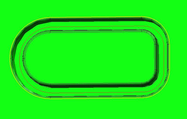
I would like the option to scan the surface following an irregular, or made up of geometric shapes curve (red) that is on that surface all the way around (sample on the picture)


 Start program dialog
PCDMIS should have some customisable deafult run program dialog. For general data inputing before measurment starts, like Operator, machine, sample number, reason for measurtment, etc.
Those dialog shoud be changeable with some Scripting editor or throu some ini file.

 Have the recent file menu show the last 10 programs executed instead of just the last 4.
Shouldn't be that hard to do. Lets get it done for 2017 guys.
Kundesupport af UserEcho


