Hexagon Measurement SystemsNo matter what Hexagon measurement equipment or software you use, we want to hear your ideas and suggestions on how we can improve.
Thanks for your assistance in helping us shape the future. |
|

 Schedule program
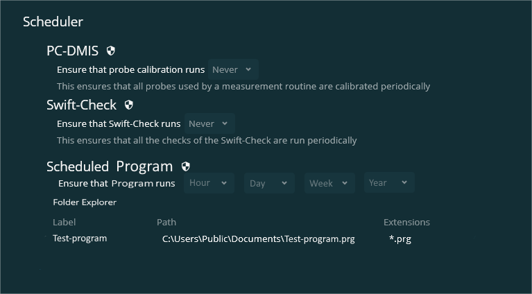
In inspect 5.1 we have been given the opportunity to schedule a calibration or Swift check. could it be possible to extend the "schedule" function so it becomes possible to schedule a specific program to run every hour, day, week or year.
see example:

 Allow serial number for each pallet cell to be scanned on barcode
In Inspect, the serial numbers (or other trace) can be entered in the pallet screen prior to measurement.
It would be useful to have an option where the serial number for each cell could be scanned in using barcode, to make this process more efficient and less error prone
Filed on behalf of a customer.

 Have the possibility to store the settings of Inspect on network
Inspect users with multiple CMM's - and who want to have the same settings (playlists, tracefields et cetera) on all the stations - are storing these settings locally on every station. This is time consuming every time they update the playlist and tracefields. Users need to update every station in this case and they loose a lot of time and make possibly erros.
It would be nice if Inspect users can store these settings on the network drive, so that you can change the playlists and tracefields from your offline station and then all your other Inspect stations are up-to-date.

 Reporting Distance Improvement for Auto_slots
Add the ability to add/ subtract widths/ lengths when reporting distance where a feature is an auto -slot. Currently we can only report to the center of the slot unless a lot of hoops are added. It's almost as common in my experience for a slot to be located to the edge instead of the center. Auto-slots are faster to code but are limited in reporting capability.

 Allow different nominals in GeoTol TP than the ones used for feature creation
With GeoTol, you cannot change/use other nominals than the ones that were used for the creation of the feature. This is good, but are problematic at times.
For example, I have a part where I am using one alignment to measure the entire thing (using CAD). This is not a problem if all the features on the drawing is dimensioned according to this one alignment, finetuning the nominals (in essence, rounding them off) is not a problem and I can get the dimensions to match the drawing for easy orientation report VS drawing.
Now, for a section of this print, the alignment has rotated 15° and the dimensions are according to this rotated view. In GeoTol, I will not get the drawings dimensions, but the dimensions are recalculated from the previous alignment to this 15° rotated alignment, meaning that I have no way to adjust the nominals to match the print (can't round them off). My only option here is to measure them IN the rotated alignment and adjust (finetune/round off) the nominals when measuring in order to get the correct nominals in GeoTol and subsequently, the report.
Getting my point?
Would it be possible to be able to change the nominals in the GeoTol evaluation (TP in this case) to use in the evaluation - not affecting the features noms (in whatever alignment they were created)? This would help immensely in situations like these, or are there a more elaborate way to use as workaround?

 I can't open the old version registered program in version 2021.2
I can't use the 2021.2 version because the programs made in the 2021.2 version of PCDMIS cannot be opened with the innovation that came in the 2021.2 version. I have a lot of prepared CMM programs. Translating them all into the new version will bring a lot of workloads. I don't know why such a feature was introduced, but there is no need to conclude a software maintenance agreement. What does the software team think.?

 Add variable function (expression builder) direct to dimension window (dialog)
Now if we want to calculate dimensions, we have to do it in multiple steps. Make a dimension, create variable with functions or operations, create a construction point, and assigned variable to that point, and report the point.
It will be more elegant if you add a checkbox to dimension window to enable and add some functions & operators to the dimension (the expression builder). The expression builder would be integrated into separate tab on all dimensional windows.

 Make an option in Inspect to have the barcode in Inspect linked to a COM port
When you have the barcode option linked to a COM port, then it always checks if there is an input from the barcode reader. Even if you're not in the input field for Inspect. With the link to a COM port, you are always sure that the routine starts.
Currently there is a hardware keyboard wege and sends the input from the barcode reader to the keyboard. It would be nicer if there is a software keyboard wedge. A software keyboard wege connects directly to the COM port and not the keyboard. Data from the barcode scanner is sent to the COM port and is rerouted to the keyboard buffer. This way you're sure that Inspect is always reading the input from the barcode scanner even if you're in another input field.

 True position tolerance add on - In Use Legacy Dimension
Dear Team,
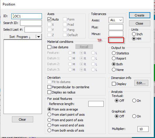
During the position tolerance callout, we don't have the separate column for position tolerance update . Instead of that every time we modifying in report callout.
In addition to +/- tolerance, if you provide the position tolerance column it would be very useful.
If any other method available in current state, please let me know.
Regards
Srinivasan N
Kundesupport af UserEcho
