Hexagon Measurement SystemsNo matter what Hexagon measurement equipment or software you use, we want to hear your ideas and suggestions on how we can improve.
Thanks for your assistance in helping us shape the future. |
|

 Thread Pitch Selection
It would be helpful to add a dropdown menu for thread pitch selection instead of requiring users to manually type in the pitch for each thread. The dropdown could include common inch and metric thread sizes, along with an option for LH threads, allowing users to quickly select the correct pitch from a list. This would save time and make the thread creation process more consistent and user-friendly
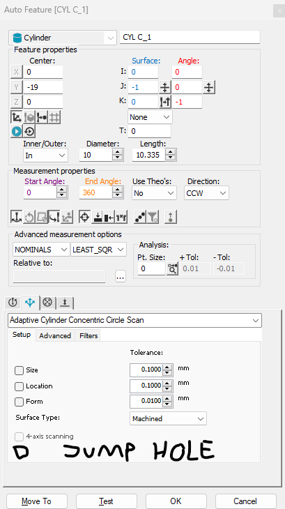
Add jump hole feature to auto cylinder and auto circle scans
Hi!
A common way of designing in certain fields is to have 2 internal cylinders to cross/pierce eachother. Therefore when choosing to scan these cylinders, having a jump hole feature same or similar to the one existing on plane scans would be of great use, instead of having to program multiple auto circles and/or cylinders. A nice additional feature to add to this would be to be able to choose to either jump by distance or angle, depending on how the part is toleranced.
Great place to have it would be in the setup window.

Ability to choose report method from Cartesian to radial or spherical on geometrical results.
We have many drawings that have surface profiles, the dimensions may apply to flat, angles, curved, radial and spherical surfaces which have BASIC controls that when reported, do not match the drawing at all, this is due to the fact that when choosing to report a surface profile, the data shown is in Cartesian and no choice for radial or spherical to report. When programming to create a new coordinate that sets the origin to a location and be able to measure radial points or surfaces, the output data needs to have the relationship to match the drawing call out, this helps with making decision on mold making, machining and or part configuration. Customers also have no correlation of results to drawing, X,Y,Z does not corollate if features are radial or spherical when looking at the surface profile point data to evaluate.

AUTO PLANE RINGS
I would like to see an option where we can adjust the distance between multiple rings when checking a radial auto plane. We of course have the option to adjust the size of the rings but, to my knowledge, don't have the option to adjust the distance between.

Comment Box Update!
I think the Comment box could use some help. I've been using PCDMIS since the 2014 version and its basically untouched in 10 years. As an offline programmer, the comments are sometimes the only way I can communicate to the inspection operators.
I have seen some people on here asking for Font Types and Colors, and i think that's a really great idea!
I would also like to see more ALT codes translated correctly to the comment box, or maybe add more than the four symbols at the bottom of the Comment Text Box. GD&T uses so many different symbols to communicate there should be a library to choose from when typing out or operator comments.
Even as I type this out, I'm looking at the options i have to edit my text and I would love to see something similar to this woven into the comment section of PCDMIS. (see below)


Possibility to disable automatic highlighting of the feature on which the cursor is located
There should be an option to disable automatic highlighting of a feature on which the cursor is placed.
When programming, the large shadow of the highlight can interfere. Especially with single circles this is a disadvantage.
At the moment there is only the possibility to change the color of the highlight.

Graphic Analysis View
Add the ability to turn off previous graphic analysis views / show one graphic analysis view at a time. Adding graphic analysis views makes the snapshot for the report cluttered and hard to read. We should be able to disable / enable graphic analysis views on dimensions in the snapshot and/or recall a viewset to "reset" the graphic view.

Inspect Slideshow - Have the ability to assign more colors
It would be good to be able to have more then just Red for failed dimension in the slideshow for inspect. I would like to see a minimum of 3 Colors. Green-passed, Yellow Warning (maybe a settable percentage), and Red Failed.

PC-DMIS restarts after n- runs
When running a palette with Inspect, it often happens that PC-DMIS slows down over time and finaly crashes.
Can a way be added, that Inspect resp. PC-DMIS is restared after n-runs?

Evaluation of Envelope Modifier (ISO 14405-1) In the Report
For reference: I'm using PC-DMIS 2020 R2 SP8.
I've been seeing the E modifier next to dimensions in recent drawings released to the ISO 14405-1 specification. When I go to look at the report to see what the two measurements (LP and GN) look like for a shaft, it appears that the lower limit is the only one that has been assigned a modifier (E) when it's clear that the upper limit was evaluated with the LP modifier and the lower limit was evaluated with the GN modifier.
My issue with the report is: it's not explicitly clear which modifier is being used. This isn't an issue for your average metrologist/CMM programmer, but to the outsider, it can be problematic and cause some confusion.
Can we have an update to the report so that when the E modifier is used, the report clearly states which modifier was used to evaluate the upper/lower limits of a shaft/hole?
I can easily work around this by reporting two separate dimensions with the appropriate modifiers for each, but I shouldn't have to do this.
خدمة دعم العملاء من خلال UserEcho