Hexagon Measurement SystemsNo matter what Hexagon measurement equipment or software you use, we want to hear your ideas and suggestions on how we can improve.
Thanks for your assistance in helping us shape the future. |
|

 PCDMIS Settings copy from public
Will be useful to have automatic procedure when we install new pcdmis release when installation procedure finish to ask if you want to copy settings or not from previous version. For example we use our own reporting and QDAS settings and always I need to copy - paste all folders from public from previous version to new.
When we install new SP we need to be careful because new installation overwrite old settings with default.

 Animation of a part program should be more realistic
We should improve PC-DMIS form a graphical animation of a mesurement routine to a kinematic simulation. Then we can also check execution times and we can see also different speeds betwenn a move and a measurment inside of a feature.

 Intervention limit for selected nominal dimension comparisons
Required: Define a separate action limit for each individual characteristic in the measuring program.
e.g: Characteristic 1 --> intervention limit 85%
Characteristic 2--> no intervention limit
Characteristic 3--> intervention limit 70%
Eingriffsgrenze für ausgewählte Nennmaßvergleiche
Es ist nur möglich eine Eingriffsgrenzen zu definieren (z.B. 80% oder 90%), die dann für alle Merkmale im Messprogramm wirksam ist.
Wunsch: Für jedes einzelne Merkmal im Messprogramm eine seperate Eingriffsgrenze definieren.
z.B.: Merkmal 1 --> Eingriffsgrenze 85%
Merkmal 2--> keine Eingriffsgrenze
Merkmal 3--> Eingriffsgrenze 70%

 "Right click delete" to remove an unwanted Windows Layout icon
Deleting an unwanted Windows Layout icon should be more intuitive.
A user should be able to simply right click and choose "delete" in a context menu to remove, not Shift-Left Mouse Click and drag away. I'd also like to be able to rearrange the order the icons appear in the toolbar.

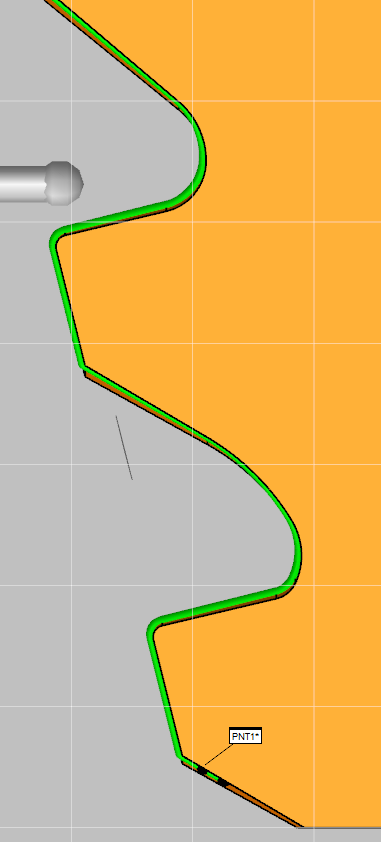
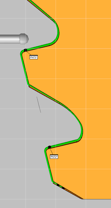
 Intersection points between curve and plane
At the moment when you construct an intersection point between plane and curve only the first intersection point (PNT1) will be construct. (see Picture 1)

We are needed every intersection point between curve and plane (PNT2 and PNT3). (see Picture 2)


 Collision Detection Speed Slide Adjustment Bar During Simulation

 Default feature color
I'd like to suggest a feature - to add an option to set the default colors for different types of features - i.e. by default every time i create a constructed feature its color on the cad model to be yellow and every time i create an auto feature its color to be red etc.
I am asking for this feature because atm whenever i start a new program or open an existing one by default all features are black and even if i set it manually the way i want it every feature i add to the program after i have set my colors is shown in black no matter where in the program i add the feature.
Also id like to suggest a global option for adjusting the features' colors for all programs because i would really like to avoid setting the colors for 1300+ programs manually one by one.
IMPO this would be extremely convenient if such an option is added to PC DMIS.

 Warning message reminder to save Program
Add a setting in the Setup Options for a save reminder. If a program is opened for a while, you will receive an warning message reminding you to save.

 QuickMeasure toolbar, make new sub icon menu
These openable icons are very useful. The new ones have been added, which is good. But I want to be able to create myself.
In this way;
- I get rid of the clutter.
- I gained from the area.
- I can make my own arrangements.

 Update scan surfaces to new model
I want an easy way to be able to bring in a new model and tell PC-DMIS to equate the surface relation of previously created scans to the new model without having to go through each scan and deselect and reselect surfaces. For example, a model revision.
Сервис поддержки клиентов работает на платформе UserEcho


