Hexagon Measurement SystemsNo matter what Hexagon measurement equipment or software you use, we want to hear your ideas and suggestions on how we can improve.
Thanks for your assistance in helping us shape the future. |
|


 Be able to see the coordinates of the mouse pointer
When I have used the scanner, I would like to see the coordinates of the pointer.
If I could, after defining the koordinatsystem, it would be very easy to check some dimensions just by hovering the pointer abow the cloud.

Give the ability to mute hits on auto-features.
Often using an auto-plane with spiral movement, asymmetrical hole patterns cause hits to land in a hole. Adjusting auto-planes manually is not fun when any slight changes require that the hits be regenerated, and you have to start back from scratch. With the ability to mute hits, you can adjust the hits by hit count and spacer, then simply mute any hits that conflict with other features.

Make the Parameter "Displayprecision" adjustable for Report Commands
At the Moment it is not possible to adjust the Displayprecision of the Reports, when the Reports are created out of the Report Command --> Print Command.
It will always use the last setting. For example: If I switch inside my PP from Displayprecision "3" to "2" and back to "3" it will use the setting "3" for the whole Report. I know this is "works as designed" but I kindly ask to make this Parameter available.
Reason I am asking this is that it is not possible to create two Reports out of one Routine (as we all know). Therefore I have to create the Report as a Report command and the use "Copy File" command in PC-DMIS to duplicate the Report. Unfortunately the Report command Report does not take over all my Displayprecision Settings as described above.
Alternatively you could make the Function available to Print the standard Report twice. For standard Reports created with "File --> Printer --> Printer Report Setting" Displayprecision works fine.
On the other Hand: When I set up different Displayprecision settings inside my Routine, why wouldnt I see it on my Report, no matter how it has been created?

Clearplane: copy/paste parameters and measurement strategies
The clearplane toggle shows up in the edit window of a feature but not in the edit window code itself, therefore you cannot copy/paste the toggle option.
Similarly, in the measurement strategy editor you cannot set the clearplane toggle to "off". I spend a lot of time updating existing programs that are much too large to reprogram from scratch. the copy/paste parameters tool has sped things up quite a bit. however you are missing the option for "Clear Plane" as well as "Measure Now".
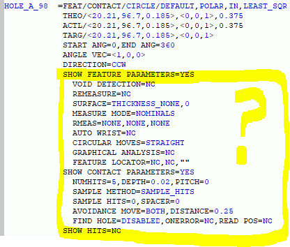
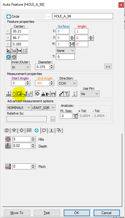
Adding a + sign to constructed features to see the points that create circles, cylinders and cones...etc..
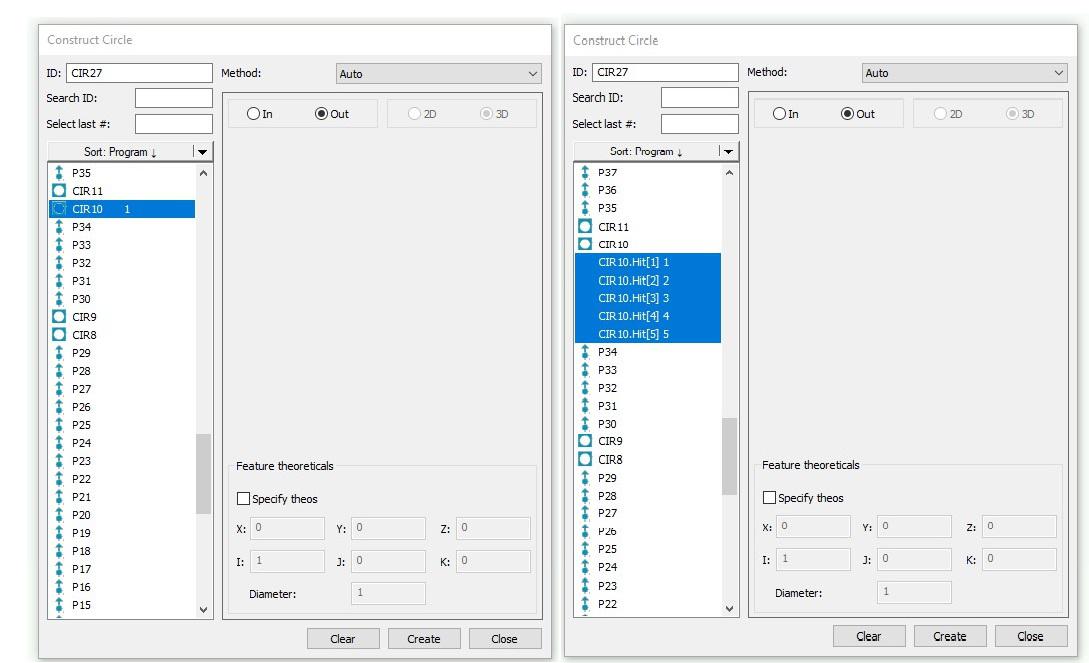
I'd like to see an option to pull the points out of a circle without having to click on the cad to do so. When i am inside my constructed feature, i wish i could just click the circle and maybe a plus sign next to it so i can get a drop down of what auto points were used to create the circle.

Ability to copy probe angles between probe assemblies
I think it would help many programmers to be able to copy selected angles from one probe assembly to another one, or at least the ability to create probe angles from the current routine. This would be especially helpful when programming since after measuring several features and have established many tip angles and needing to change what probe is used due to a limitation for whatever reason. ive come across this scenario multiple times already and figured this might be helpful to others.

Сервис поддержки клиентов работает на платформе UserEcho
