Hexagon Measurement SystemsNo matter what Hexagon measurement equipment or software you use, we want to hear your ideas and suggestions on how we can improve.
Thanks for your assistance in helping us shape the future. |
|

 Allow evaluation of angularity and perpendicularity vs 3 datums and MMC/LMC modifier to said datums with ISO1101 settings
Hi PC-DMIS team and users.
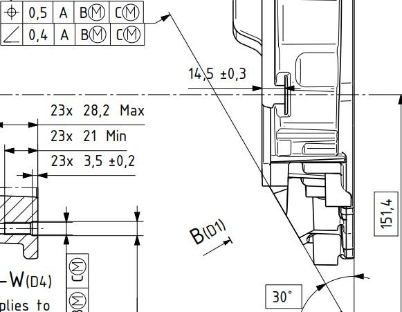
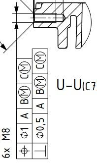
I have time to time encountered requirements that call out for angularity and perpendicularity versus 3 datums. Since PC-DMIS currently doesnt allow this, i have researched about it with my local PC-DMIS provider (Hexagon Sweden) and my employers ISO experts, who are part of the ISO committee. According to both Hexagon Sweden and the mentioned ISO experts, both perpendicularity and angularity, although not very clearly described in ISO1101 currently, are fully intended to be used with a complete datum system such as A B C, which is confirmed with the people who participated in writing the current version of ISO1101.
It is to my understanding that this would be equal to, or very similar atleast, to be using surface profile with a complete datum system but with the OZ modifier applied. This is my current workaround when i see such requirements on flat surfaces. But when the requirement applies to a bore
or a shaft, this workaround no longer works and i have no proper way to do it.
In addition to implementing a change like this, a yellow text warning, similar to the warning text to [DF] modifier could be used as soon as the 3rd datum is defined. Where the text implies that a 3rd datum for angularity and perpendicularity is not clearly described in ISO1101, and also asks the user to consider if this is really the intended requirement for the feature, or something along those lines.
In addition to this, bring back the ability to add the LMC and MMC modifier for the datums used for the angularity/perpendicularity evaluations. There is nothing stated that prohibits this in current standards. It is allowed for surface profile with OZ modifier, so after all, why shouldn't it be allowed to be used for angularity and perpendicularity.
If you need any further clarification or explanation, im happy to fill in. Thanks!
Below are 2 example pictures from the same technical drawing.

Report template: When is it possible to insert the scan on the 3D CAD with the individual points (T-difference) also in the report as a 3D image with the deviations visible?
It is also possible to click on individual points and have the deviation displayed directly in the report.

Add mark used and global used as parameter set options for Auto Calibrate
Add Mark used and Global used as parameter set options for Auto Calibrate.
Doing this could eliminate the possibility of forgetting to update the Parameter set when the tips used in a measurement routine is updated.
Path Lines Shortcut Key
Function of ALT+P, or another shortcut key, to turn path lines on for highlighted code instead of all instead of having to right click to select

Transform the CAD
Add more tools to easy manipulate the CAD; Sometimes I get the Model with crazy angles, and it is too complicate to transform it


Search bar for settings
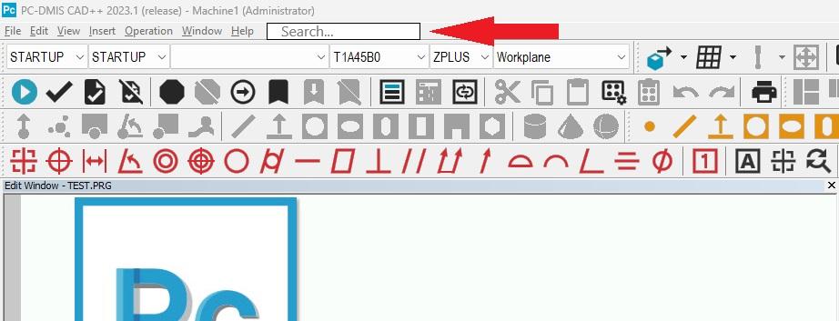
Add a search bar for settings at the top of the software.
I can't tell you how long I have had to search for Excel Form Report, analysis, screen capture to file, etc.

Distance-to-go while executing a program
When executing a program, not much information is available to you, and knowing how far a probe is about to travel is a great indicator of whether or not you're in the right ballpark.
Simply a value showing how far the probe is going to move before it reaches the point in which it will switch to touch speed or begin moving in another direction.
We see more and more machinist being trained to run PC-DMIS, and this is a comfortable feature they're used to seeing when running their CNC machines. I think it could help prevent many CMM crashes.

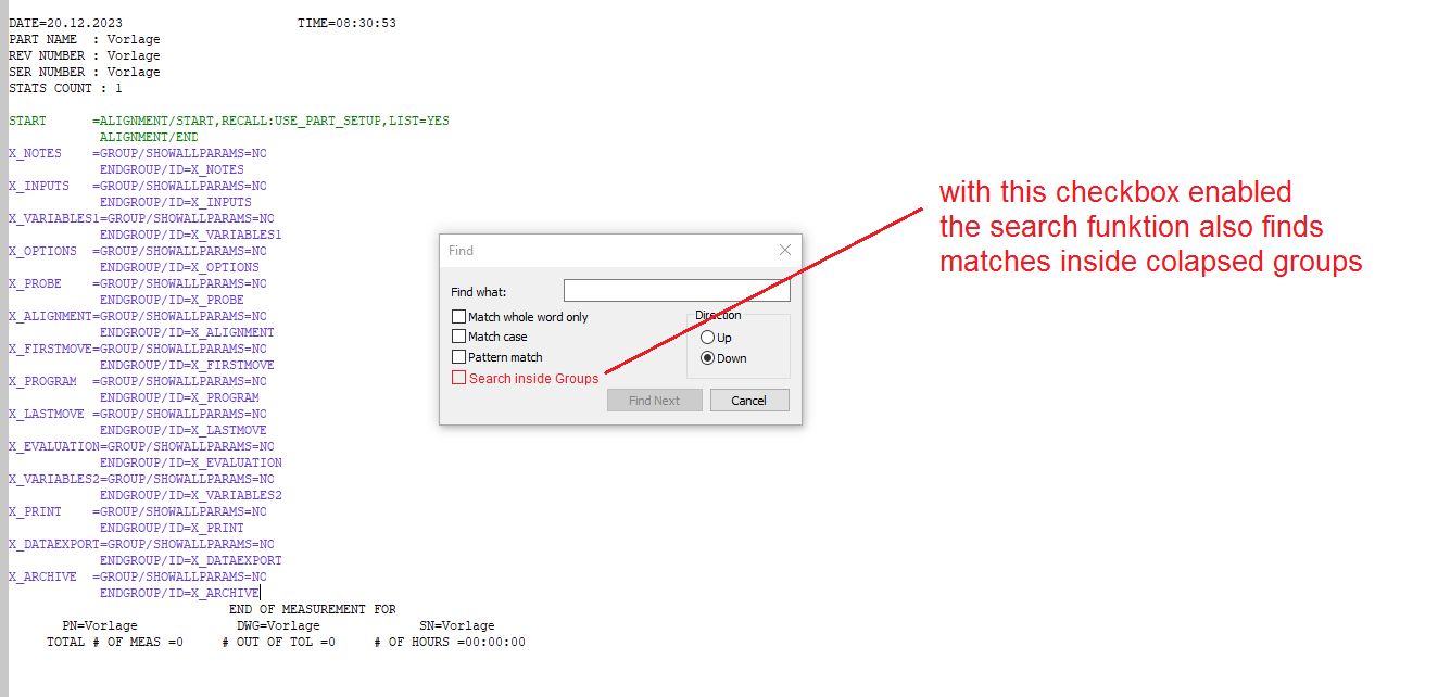
enhance search function for groups
Problem:
The group function is often used to keep the routine tidy and organized.
But when you have "collapsed" groups in your measurement routine, the search function doesn't show matches inside of them. The user needs to open all groups first to use the search.
This is very time-consuming. Inexperienced users may not know that they have to open the groups first.
Solution:
Add a checkbox to the search function called "Search inside groups" or similar.
When checked, the search function also looks inside groups for matches.

Zoom on initialization Optiv
On initialization of the Optic measuring device, the camera is always zoomed completely on maximum zoom.
This makes it hard to find my piece. I first need to zoom out completely, before I can start.
For me, I prefer to start with zoom on minimum, but maybe someone likes to start with zoom on maximum.
Can there be an update where we can have that choice?
Customer support service by UserEcho