Hexagon Measurement SystemsNo matter what Hexagon measurement equipment or software you use, we want to hear your ideas and suggestions on how we can improve.
Thanks for your assistance in helping us shape the future. |
|


 Easy access to axis data of geometric tolerance commands
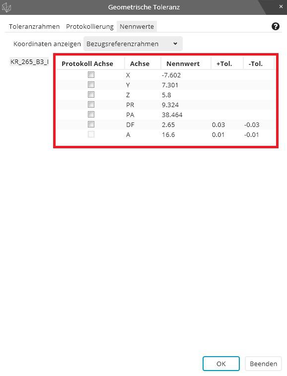
Make it easy for the user to have access to all axis data inside the geometric tolerance command via variables.
We used to have the option to write "FCFLOC1.X.MEAS" while this syntax still works it only works if just one feature is selected inside the geometric tolerance command.
The new syntax is "FCFLOC1.SEGMENT[1].FEATURE[1].MEAS" while we can change the feature number to get the different measurement values there is no possibility to get the axis data of the features.
My proposal is to let the user add the axis letter(s) before the ".MEAS" or ".DEV" to indicate which axis he wants extracted. If no letter is indicated the syntax behaves as before.
The syntax should work with all available axis letters not only the ones shown on the report.
Examples:
"FCFLOC1.SEGMENT[1].FEATURE[2].X.MEAS"
"FCFLOC2.SEGMENT[1].FEATURE[5].Y.DEV"
"FCFLOC3.SEGMENT[1].FEATURE[3].PA.DEV"

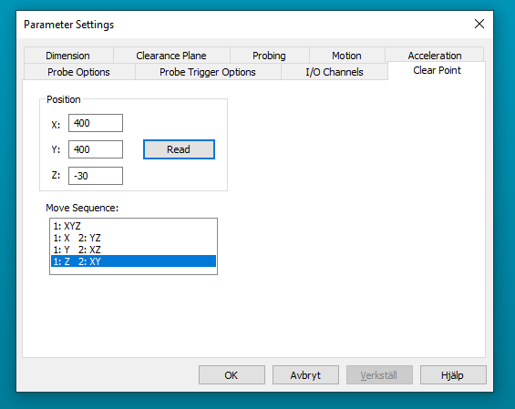
Ability ta add multiple clear points
It would be good to have the ability to add multiple clear points and to configure them individually regarding the axis movement order.

Backwards compatability with Xact
Want backwards compatibility with Xact measure for GD&T. I have hundreds of programs that would need to be reviewed. I'm in a regulated industry and can just imagine the chaos that would happen with changing to the new scheme. I appreciate the effort and improvements in the update to the new scheme. However, the costs and headaches involved in ensuring that older programs will provide the same results are going to hold us back. I have gotten around updating previous release updates by arguing that the changes are relatively minor and are mainly programming aids. This is a major change.
Other alternative would be a way to not allow Xact measurement routines to not run at all.
Late to the party and realize it's probably not possible but still....

Add the option to report out postion of both start and end pts of a cylinder instead of only the worst end. Legacy had this option but the GD&T reporting does not.
By showing both it gives a good indication of how angled the cylinder may be.

INSPECT Slideshow - possibility to add additional lines for better assignment of e.g. distance features.
i am currently working in inspect 5.1
Currently, the slideshow does not display well angle, distances etc. that refer to more than one element.
Is it planned to imply the possibility of additional dimension lines?


Inspect Pallet Playlist add multiple pallets with spacing controls
Many customers have large enough machines and smaller parts facilitating the ability to load multiple fixtures on the machine. It would be helpful to have the ability to specify spacing between fixtures to execute sequentially.
This could possibly be done with fixture alignments rather than spacing for provision where the spacing may not be uniform.

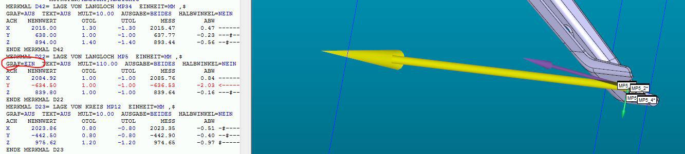
Vectors of deviation in CAD protocol
Hello,
we need to have the option to show the vectors of the deviation in our protocol.
It is possible in the graphical window in PC-DMIS, so why isnt it possible in the "CADONLY" protocol e.g.?
Here is a screenshot what I mean:
Thanks in advance

2021.1__Add unequal tolerance zones for analysis view command
Using 2021.1, an "analysisview" command of a feature control frame that uses the "U Modifier" will ONLY allow us to put on the inspection report an "analysisview" of a BILATERAL tolerance band.
Please add the capability for us to show the tolerance band as UNEQUAL.

summary view, color scheme, similar to edit window colors
add a color scheme to the summary view, similar to the edit window color scheme that can be saved and recalled.
Customer support service by UserEcho
