Hexagon Measurement SystemsNo matter what Hexagon measurement equipment or software you use, we want to hear your ideas and suggestions on how we can improve.
Thanks for your assistance in helping us shape the future. |
|

 Quicker Tech services. If I have an issue happening and I need to the know the solution now, I cant wait in a queue for hours.-

 Excel Form Report, PCD ID |x||y||z| output
In excel form report, can we implement where the xyz values will run in a row for a dimension, and than in the next row below it another dimension and it's xyz values, and so on and so forth.
Example:
Row1: |X|,|Y|,|Z|,|PCD ID|
Row2: |X|,|Y|,|Z|,|PCD ID|
Row3: |X|,|Y|,|Z|,|PCD ID|
etc.

 Streamline Dimensioning
I feel like a lot of features have been upgrade or streamlined to make them as easy or possible to use, but dimensioning has been left behind. For example if I have a lot of dimensions coming from Datum A I have to click on Datum A every time I want to Dimension from that. I know I could make that my zero then report the locations but some of our customers are very particular about cmm reports.
We should have an option to Keep datum A selected and only have to select what we want the dimension to go to. This would save some time and some clicking.
Thats the only idea I have for now but im sure other people have other ideas for this.

 Locking a feature label to
I would like to be able to select feature labels to stay in the view in the camera while dimensioning. For example if the part is really big but all the dimensions come from Datum A it would be nice to have the datum A feature label always in the camera view to easily select it. Right now can drag the label around but this would be much easier. The same way we can lock and unlock targets on the vision systems

 Auto Close Program
The ability to add a line of code that would automatically file>close or file quit a program.
Similar to routine end.

 Construct a line from a circle
We want the ability to construct a line from a circle by drawing a line perpendicular to the plane through the centrum line

 Zeiss Calypso RDS-CAA function for Hexagon CMMs (HH-AS8-T2.5)
Need the ability to calibrate a set of probe tip angles and the software calculate to the calibration for the rest of the tip angle possibilities, the RDS probe head using the CAA (computer aided accuracy) calibration function save hours of calibration time by not having to calibrate each tip angle across multiple jobs and accurate enough for most dimensions.

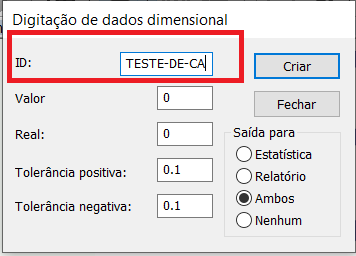
 Quantidade de Caracteres nos ID dos elementos
Atualmente só é possível descrever as identificações dos elementos com no máximo 11 caracteres, seria interessante aumentar a quantidade de caracteres permitidos, assim poderia identificar melhor cada elemento da peça.


 Add Laser functions to the Measurement Strategy Editor
Add the strategies for laser extractions/direct measurements to the MSE to increase efficiency and add PMI capability.
Customer support service by UserEcho


