Hexagon Measurement SystemsNo matter what Hexagon measurement equipment or software you use, we want to hear your ideas and suggestions on how we can improve.
Thanks for your assistance in helping us shape the future. |
|


 Import new cad (step) use current program
I have a new REV and I want to Import the newest CAD (STEP FILE) and use the same program I've already written. Can anyone advise? Thank you.

create assemblies with mating parts instead of coordinates
By using CAD models, mate parts together the way Solidworks does. It has the ability to click mating center points to lock the XY and the click two mating faces to lock the Z. This would make it easier instead of inputting a XYZ coordinate move.
Transform but use select center
Have the ability to transform the cad to center the datums on a hole using a select center option instead of using a coordinate system. This would make it easier so I don't have to trig it out.

PC-DMIS, Inspect or both, be able to simplify the Part input information and the Folder and multi reporting creation with a file exists notification.
Question: When will PC-DMIS, Inspect or both, be able to simplify the Part input information and the Folder and multi reporting creation with a file exists notification. This will help me to replace most of this code in the template.
COMPONENT_REPORT_ID=GROUP/SHOWALLPARAMS=YES
COMPONENT_REPORT_ID_START_L1 =LABEL/
$$ NO,
Component Report ID Controls.
Place where to start recording
features and dimensions
.
$$ NO,
REPORT PART INFO AND PROBE READ OUT WINDOW INFO
.===============================================.
2018 R2 and up
""+GETTEXT(1072,1,COMMAND_V1)+" "+GETTEXT(258,1,COMMAND_V1)
2016 older
""+GETTEXT(257,1,COMMAND_V1)+" "+GETTEXT(258,1,COMMAND_V1)
IF/COMMENT_VISUAL_V1=="YES"
COMMENT/REPT,
""+GETTEXT(1072,1,COMMAND_V1)+" "+GETTEXT(258,1,COMMAND_V1)
COMMENT/READOUTS,NO,
""+GETTEXT(1072,1,COMMAND_V1)+" "+GETTEXT(258,1,COMMAND_V1)
END_IF/
IF/COMMENT_VISUAL_V2=="YES"
COMMENT/REPT,
""+GETTEXT(1072,1,COMMAND_V2)+" "+GETTEXT(258,1,COMMAND_V2)
COMMENT/READOUTS,NO,
""+GETTEXT(1072,1,COMMAND_V2)+" "+GETTEXT(258,1,COMMAND_V2)
END_IF/
IF/COMMENT_VISUAL_V3=="YES"
COMMENT/REPT,
""+GETTEXT(1072,1,COMMAND_V3)+" "+GETTEXT(258,1,COMMAND_V3)
COMMENT/READOUTS,NO,
""+GETTEXT(1072,1,COMMAND_V3)+" "+GETTEXT(258,1,COMMAND_V3)
END_IF/
IF/COMMENT_VISUAL_V4=="YES"
COMMENT/REPT,
""+GETTEXT(1072,1,COMMAND_V4)+" "+GETTEXT(258,1,COMMAND_V4)
COMMENT/READOUTS,NO,
""+GETTEXT(1072,1,COMMAND_V4)+" "+GETTEXT(258,1,COMMAND_V4)
END_IF/
IF/COMMENT_VISUAL_V5=="YES"
COMMENT/REPT,
""+GETTEXT(1072,1,COMMAND_V5)+" "+GETTEXT(258,1,COMMAND_V5)
COMMENT/READOUTS,NO,
""+GETTEXT(1072,1,COMMAND_V5)+" "+GETTEXT(258,1,COMMAND_V5)
END_IF/
IF/COMMENT_VISUAL_V6=="YES"
COMMENT/REPT,
""+GETTEXT(1072,1,COMMAND_V6)+" "+GETTEXT(258,1,COMMAND_V6)
COMMENT/READOUTS,NO,
""+GETTEXT(1072,1,COMMAND_V6)+" "+GETTEXT(258,1,COMMAND_V6)
END_IF/
IF/COMMENT_VISUAL_V7=="YES"
COMMENT/REPT,
""+GETTEXT(1072,1,COMMAND_V7)+" "+GETTEXT(258,1,COMMAND_V7)
COMMENT/READOUTS,NO,
""+GETTEXT(1072,1,COMMAND_V7)+" "+GETTEXT(258,1,COMMAND_V7)
END_IF/
IF/COMMENT_VISUAL_V8=="YES"
COMMENT/REPT,
""+GETTEXT(1072,1,COMMAND_V8)+" "+GETTEXT(258,1,COMMAND_V8)
COMMENT/READOUTS,NO,
""+GETTEXT(1072,1,COMMAND_V8)+" "+GETTEXT(258,1,COMMAND_V8)
END_IF/
IF/COMMENT_VISUAL_V9=="YES"
COMMENT/REPT,
""+GETTEXT(1072,1,COMMAND_V9)+" "+GETTEXT(258,1,COMMAND_V9)
COMMENT/READOUTS,NO,
""+GETTEXT(1072,1,COMMAND_V9)+" "+GETTEXT(258,1,COMMAND_V9)
END_IF/
IF/COMMENT_VISUAL_V10=="YES"
COMMENT/REPT,
""+GETTEXT(1072,1,COMMAND_V10)+" "+GETTEXT(258,1,COMMAND_V10)
COMMENT/READOUTS,NO,
""+GETTEXT(1072,1,COMMAND_V10)+" "+GETTEXT(258,1,COMMAND_V10)
END_IF/
IF/COMMENT_VISUAL_V11=="YES"
COMMENT/REPT,
""+GETTEXT(1072,1,COMMAND_V21)+" "+GETTEXT(258,1,COMMAND_V21)
COMMENT/READOUTS,NO,
""+GETTEXT(1072,1,COMMAND_V21)+" "+GETTEXT(258,1,COMMAND_V21)
END_IF/
COMMENT/REPT,
~~1______________________________________________ REPORT _____________________________________________
$$ YES,
_
$$ NO,
Stats Controller
IF/USE_STATS_CONTROLLER=="YES"
$$ NO,
Stats commands
IF/STATS_COMMAND_V1=="YES"
COMMENT/OPER,NO,FULL SCREEN=NO,AUTO-CONTINUE=NO,
Add Stats Command. Remove any External Stats Command.
END_IF/
$$ NO,
External Stats Command
IF/EXTERNAL_COMMAND_V1=="YES"
$$ NO,
Add External Stats Command. Remove any Stats Command.
IF/VIEW_DATABASE_COMMENT=="YES"
SKIP_STATS_REPORT_COMMENT_C1 =COMMENT/YESNO,NO,FULL SCREEN=NO,AUTO-CONTINUE=YES,TIME DELAY=2,
Continue using Database Stats?
IF_GOTO/SKIP_STATS_REPORT_COMMENT_C1.INPUT=="NO",GOTO = SKIP_STATS_REPORT_COMMENT_L1
$$ NO,
Operator comment using Auto-continue is needed for a time delay
for the External Command.
END_IF/
EXTERNALCOMMAND/NO_DISPLAY, NO_WAIT ; C:\PROGRAM FILES (X86)\HEXAGON\DATAPAGE+ 5.2\DATAPAGESTATS.EXE -LISTENING
COMMENT/OPER,YES,FULL SCREEN=NO,AUTO-CONTINUE=YES,TIME DELAY=2,
Starting Database Stats.
END_IF/
TRACEFIELD/DISPLAY=NO,REPORT=NO,DISPLAY MESSAGE=COMMENT_V1 ; COMMENT_V1 : GETTEXT(258,1,COMMAND_V1)
TRACEFIELD/DISPLAY=NO,REPORT=NO,DISPLAY MESSAGE=COMMENT_V2 ; COMMENT_V2 : GETTEXT(258,1,COMMAND_V2)
TRACEFIELD/DISPLAY=NO,REPORT=NO,DISPLAY MESSAGE=COMMENT_V3 ; COMMENT_V3 : GETTEXT(258,1,COMMAND_V3)
TRACEFIELD/DISPLAY=NO,REPORT=NO,DISPLAY MESSAGE=COMMENT_V4 ; COMMENT_V4 : GETTEXT(258,1,COMMAND_V4)
TRACEFIELD/DISPLAY=NO,REPORT=NO,DISPLAY MESSAGE=COMMENT_V5 ; COMMENT_V5 : GETTEXT(258,1,COMMAND_V5)
TRACEFIELD/DISPLAY=NO,REPORT=NO,DISPLAY MESSAGE=COMMENT_V6 ; COMMENT_V6 : GETTEXT(258,1,COMMAND_V6)
TRACEFIELD/DISPLAY=NO,REPORT=NO,DISPLAY MESSAGE=COMMENT_V7 ; COMMENT_V7 : GETTEXT(258,1,COMMAND_V7)
TRACEFIELD/DISPLAY=NO,REPORT=NO,DISPLAY MESSAGE=COMMENT_V8 ; COMMENT_V8 : GETTEXT(258,1,COMMAND_V8)
TRACEFIELD/DISPLAY=NO,REPORT=NO,DISPLAY MESSAGE=COMMENT_V9 ; COMMENT_V9 : GETTEXT(258,1,COMMAND_V9)
TRACEFIELD/DISPLAY=NO,REPORT=NO,DISPLAY MESSAGE=COMMENT_V10 ; COMMENT_V10 : GETTEXT(258,1,COMMAND_V10)
TRACEFIELD/DISPLAY=NO,REPORT=NO,DISPLAY MESSAGE=COMMENT_V11 ; COMMENT_V11 : GETTEXT(258,1,COMMAND_V21)
SKIP_STATS_REPORT_COMMENT_L1 =LABEL/
END_IF/
COMPONENT_REPORT_ID_END_L1 =LABEL/
ENDGROUP/ID=COMPONENT_REPORT_ID
PROGRAM_CONTROLS=GROUP/SHOWALLPARAMS=YES
$$ NO,
Report Template Pro version
$$ NO,
Program Controls Start
.~~~~~~~~~~~~~~~~~~~~~~~~~~~~~~.
$$ NO,
Component ID Controls Start
.==============================.
GOTO/COMPONENT_ID_CTRL_END1
COMPONENT_ID_CTRL_START1 =LABEL/
$$ NO,
NOTE:
After changing variable settings for Trace Fields, Save, Close Routine and Reopen Routine.
.
Assign values below are used for copy and paste only.
ASSIGN/YES_V1="YES"
ASSIGN/NO_V1="NO"
ASSIGN/RTP_V1=".RTF"
ASSIGN/PDF_V1=".PDF"
ASSIGN/3DPDF_V1=".3DPDF"
ASSIGN/TXT_V1=".TXT"
ASSIGN/TEXTONLY_V1="TEXTONLY.RTP"
ASSIGN/TEXTONLY_HEADER_EVERY_PAGE_V1="TEXTONLY_Header_Every_Page.RTP"
ASSIGN/TEXTANDCAD_V1="TEXTANDCAD.RTP"
ASSIGN/CADONLY_V1="CADONLY.RTP"
ASSIGN/GRAPHICALANALYSIS_V1="GRAPHICALANALYSIS.RTP"
ASSIGN/CADONLY_LANDSCAPE_V1="CADONLY_LANDSCAPE.RTP"
ASSIGN/PPAP_V1="PPAP.RTP"
ASSIGN/PLAINTEXT_V1="PlainText.rtp"
ASSIGN/TEXTANDCAD_OOT_V1="TEXTANDCAD_OOT.RTP"
ASSIGN/FORM_PLOT_V1="Form Plot.rtp"
ASSIGN/DEFAULT_V1="default.rtp"
$$ NO,
Clearpoint - Use Start Clearpoint settings
ASSIGN/USE_START_CLEARPOINT="YES"
$$ NO,
Clearpoint - View Start Clearpoint Commemt settings
ASSIGN/VIEW_START_CLEARPOINT_COMMENT="YES"
$$ NO,
Clearpoint - Use End Clearpoint settings
ASSIGN/USE_END_CLEARPOINT="YES"
$$ NO,
Clearpoint - View End Clearpoint Comment settings
ASSIGN/VIEW_END_CLEARPOINT_COMMENT="NO"
$$ NO,
Excel Form Report - Use Excel Form Report (Hard code for part reporting file exist backup)
ASSIGN/USE_EXCEL_FORM_REPORT_BACKUP="YES"
$$ NO,
Excel Form Report - (Hard code file location for part reporting file exist backup)
Excel Form Report File name format will use the Per Part Report format
ASSIGN/EXCEL_FORM_REPORT_BACKUP_FILE_LOC="C:\Users\Public"
$$ NO,
Manual Alignment - Use DCC move to a safe clear path for execution setting
ASSIGN/USE_DCC_MOVE_FROM_MAN="YES"
$$ NO,
Report footer - Contoller settings
ASSIGN/USE_REPORT_FOOTER_CONTROL="YES"
$$ NO,
Report footer - viewer settings
ASSIGN/VIEW_REPORT_VIEWER="YES"
$$ NO,
Report - Control setting
ASSIGN/USE_PRINT_COMMAND_ALT="NO"
$$ NO,
Report - Current Report Path - Report Template
ASSIGN/CURRENT_REPORTING_TEMPLATE_PATH=PCDMISSYSTEMREPORTINGPATH()
$$ NO,
Report - Format print settings - Edit the Print Command format - (Default .TXT)
.Warnig: When using the same file format as the Basic print
.the printing procees will append both reports
.
(Default - Use this report printing for text report backup using File Exist.)
(Example folder name is Part Number PC-DMIS Reports)
.
. .RTF .
. .PDF .
. .3DPDF . This is only used for variable value
. .TXT .
ASSIGN/PRINT_FORMAT=".TXT"
$$ NO,
Report - Report Template settings - (Default TEXTONLY.RTP)
.Warnig: When using the same file format as the Basic print
.the printing procees will append both reports
.
. TEXTONLY.RTP .
. TEXTONLY_Header_Every_Page.RTP .
. TEXTANDCAD.RTP .
. CADONLY.RTP .
. GRAPHICALANALYSIS.RTP .
. CADONLY_LANDSCAPE.RTP .
. PPAP.RTP .
. PlainText.rtp .
. TEXTANDCAD_OOT.RTP .
. Form Plot.rtp .
. default.rtp .
.
ASSIGN/PRINT_REPORT_TEMPLATE="TEXTONLY.RTP"
$$ NO,
Report - part description settings
ASSIGN/COMMENT_V1="Part ID"
ASSIGN/COMMENT_V2="Rev Number"
ASSIGN/COMMENT_V3="Lot Number"
ASSIGN/COMMENT_V4="Serial Number"
ASSIGN/COMMENT_V5="Cavity"
ASSIGN/COMMENT_V6="Category"
ASSIGN/COMMENT_V7="Operator"
ASSIGN/COMMENT_V8="Machine Recall ID"
ASSIGN/COMMENT_V9="Notes"
ASSIGN/COMMENT_V10="Date Code"
ASSIGN/COMMENT_V11="Date"
$$ NO,
Report - part description and Read out view settings
ASSIGN/COMMENT_VISUAL_V1="YES"
ASSIGN/COMMENT_VISUAL_V2="YES"
ASSIGN/COMMENT_VISUAL_V3="YES"
ASSIGN/COMMENT_VISUAL_V4="YES"
ASSIGN/COMMENT_VISUAL_V5="YES"
ASSIGN/COMMENT_VISUAL_V6="YES"
ASSIGN/COMMENT_VISUAL_V7="YES"
ASSIGN/COMMENT_VISUAL_V8="YES"
ASSIGN/COMMENT_VISUAL_V9="YES"
ASSIGN/COMMENT_VISUAL_V10="YES"
ASSIGN/COMMENT_VISUAL_V11="YES"
$$ NO,
Report - part descriptions output format
ASSIGN/COMMENT_V1A=COMMENT_V1+":"
ASSIGN/COMMENT_V2A=COMMENT_V2+":"
ASSIGN/COMMENT_V3A=COMMENT_V3+":"
ASSIGN/COMMENT_V4A=COMMENT_V4+":"
ASSIGN/COMMENT_V5A=COMMENT_V5+":"
ASSIGN/COMMENT_V6A=COMMENT_V6+":"
ASSIGN/COMMENT_V7A=COMMENT_V7+":"
ASSIGN/COMMENT_V8A=COMMENT_V8+":"
ASSIGN/COMMENT_V9A=COMMENT_V9+":"
ASSIGN/COMMENT_V10A=COMMENT_V10+":"
ASSIGN/COMMENT_V11A=COMMENT_V11+":"
$$ NO,
Routine - Date and Time settings
ASSIGN/DATE_V1=SYSTEMDATE("MM/dd/yyyy")
ASSIGN/DATE_V2=SYSTEMDATE("MM-dd-yyyy")
ASSIGN/DATE_V3=SYSTEMDATE("MM.dd.yyyy")
$$ NO,
Setup Contols - Use Comments and External Setups
ASSIGN/USE_EXTERNAL_SETUP="NO"
ASSIGN/USE_COMMENT_SETUP="YES"
$$ NO,
Stats - Controller settings(Default "YES" for Excel reporting)
ASSIGN/USE_STATS_CONTROLLER="YES"
$$ NO,
Stats - Command settings
ASSIGN/STATS_COMMAND_V1="NO"
$$ NO,
Stats - External Stats Command settings
ASSIGN/EXTERNAL_COMMAND_V1="NO"
$$ NO,
Stats - View and lock out the Database Stats comment settings.
ASSIGN/VIEW_DATABASE_COMMENT="YES"
$$ NO,
View component window settings
ASSIGN/VIEW_START_MENU="YES"
$$ NO,
Routine Controller Start Menu
CONTROLLER_WINDOW_START1 =LABEL/
IF_GOTO/VIEW_START_MENU=="NO",GOTO = SKIP_START_MENU_L1
TRACEFIELD/DISPLAY=YES,REPORT=NO,DISPLAY MESSAGE=COMMENT_V11A ; COMMENT_V11A : DATE_V2
TRACEFIELD/DISPLAY=YES,REPORT=NO,DISPLAY MESSAGE=Execute Program in DCC mode? (Use Skip after measuring a Part Datum Location Fixture): ; DCC : Yes
TRACEFIELD/DISPLAY=YES,REPORT=NO,DISPLAY MESSAGE=Execute Program in Manual mode? ; MANUAL : Yes
TRACEFIELD/DISPLAY=YES,REPORT=NO,DISPLAY MESSAGE=Include Setup mode? ; SETUP : Yes
TRACEFIELD/DISPLAY=YES,REPORT=NO,DISPLAY MESSAGE=COMMENT_V1A ; COMMENT_V1A : CFI0000
TRACEFIELD/DISPLAY=YES,REPORT=NO,DISPLAY MESSAGE=COMMENT_V2A ; COMMENT_V2A : CFI1
TRACEFIELD/DISPLAY=YES,REPORT=NO,DISPLAY MESSAGE=COMMENT_V3A ; COMMENT_V3A : 0000D00
TRACEFIELD/DISPLAY=YES,REPORT=NO,DISPLAY MESSAGE=COMMENT_V4A ; COMMENT_V4A : CFI1
TRACEFIELD/DISPLAY=YES,REPORT=NO,DISPLAY MESSAGE=COMMENT_V5A ; COMMENT_V5A : 1
TRACEFIELD/DISPLAY=YES,REPORT=NO,DISPLAY MESSAGE=COMMENT_V6A ; COMMENT_V6A : DIP Report
TRACEFIELD/DISPLAY=YES,REPORT=NO,DISPLAY MESSAGE=COMMENT_V7A ; COMMENT_V7A : DIM INSP
TRACEFIELD/DISPLAY=YES,REPORT=NO,DISPLAY MESSAGE=COMMENT_V8A ; COMMENT_V8A : 3435_3271_5472_5473_3436
TRACEFIELD/DISPLAY=YES,REPORT=NO,DISPLAY MESSAGE=COMMENT_V9A ; COMMENT_V9A : G_E_SF_T_X
TRACEFIELD/DISPLAY=YES,REPORT=NO,DISPLAY MESSAGE=COMMENT_V10A ; COMMENT_V10A : Report
TRACEFIELD/DISPLAY=YES,REPORT=NO,DISPLAY MESSAGE=Use Manual Keyin Dimensions ; KEYIN_DIM : No
TRACEFIELD/DISPLAY=YES,REPORT=NO,DISPLAY MESSAGE=View Routine End Comments ; VIEW_COMMENTS : No
TRACEFIELD/DISPLAY=YES,REPORT=NO,DISPLAY MESSAGE=Use Custum File Name (For Print Command reports only) ; CUSTOM_FILE : No
TRACEFIELD/DISPLAY=YES,REPORT=NO,DISPLAY MESSAGE=Custom File Name ; CUSTOM_FILE_NAME : CFI0000_CFI1
TRACEFIELD/DISPLAY=YES,REPORT=NO,DISPLAY MESSAGE=Save Reports (No, Excel, Report or Both(Recommended)) ; SAVE_REPORTS : No
TRACEFIELD/DISPLAY=YES,REPORT=NO,DISPLAY MESSAGE=Report Method (Per-Part, Part Append(Excel only) or Both) ; REPORT_METHOD : Part Append
TRACEFIELD/DISPLAY=YES,REPORT=NO,DISPLAY MESSAGE=Save Out of Tolerance (OUTTOL) Report ; SAVE_OUTTOL_REPORT : No
TRACEFIELD/DISPLAY=YES,REPORT=NO,DISPLAY MESSAGE=Create a new Folder File location ; REPORT_FILE : Yes
SKIP_START_MENU_L1 =LABEL/
$$ NO,
Start menu GetCommand section
ASSIGN/COMMAND_V1=GETCOMMAND(191,"UP",18)
ASSIGN/COMMAND_V2=GETCOMMAND(191,"UP",17)
ASSIGN/COMMAND_V3=GETCOMMAND(191,"UP",16)
ASSIGN/COMMAND_V4=GETCOMMAND(191,"UP",15)
ASSIGN/COMMAND_V5=GETCOMMAND(191,"UP",14)
ASSIGN/COMMAND_V6=GETCOMMAND(191,"UP",13)
ASSIGN/COMMAND_V7=GETCOMMAND(191,"UP",12)
ASSIGN/COMMAND_V8=GETCOMMAND(191,"UP",11)
ASSIGN/COMMAND_V9=GETCOMMAND(191,"UP",10)
ASSIGN/COMMAND_V10=GETCOMMAND(191,"UP",9)
ASSIGN/COMMAND_V11=GETCOMMAND(191,"UP",8)
ASSIGN/COMMAND_V12=GETCOMMAND(191,"UP",7)
ASSIGN/COMMAND_V13=GETCOMMAND(191,"UP",19)
ASSIGN/COMMAND_V14=GETCOMMAND(191,"UP",20)
ASSIGN/COMMAND_V15=GETCOMMAND(191,"UP",21)
ASSIGN/COMMAND_V16=GETCOMMAND(191,"UP",6)
ASSIGN/COMMAND_V17=GETCOMMAND(191,"UP",5)
ASSIGN/COMMAND_V18=GETCOMMAND(191,"UP",4)
ASSIGN/COMMAND_V19=GETCOMMAND(191,"UP",3)
ASSIGN/COMMAND_V20=GETCOMMAND(191,"UP",1)
ASSIGN/COMMAND_V21=GETCOMMAND(191,"UP",22)
ASSIGN/COMMAND_V22=GETCOMMAND(191,"UP",2)
IF/GETTRACEVALUE("DCC")=="No" AND GETTRACEVALUE("MANUAL")=="No" AND GETTRACEVALUE("SETUP")=="No"
COMMENT/OPER,NO,FULL SCREEN=NO,AUTO-CONTINUE=NO,
No selection made.
Selections must have at least one Yes to continue for DCC, Manual or setup.
GOTO/CONTROLLER_WINDOW_START1
END_IF/
IF/GETTRACEVALUE("DCC")=="No" AND GETTRACEVALUE("MANUAL")=="No" AND GETTRACEVALUE("SETUP")=="Yes"
GOTO/ROUTINE_SETUP_CTRL_START1
END_IF/
ASSIGN/BLANK_V1=0
IF/GETTRACEVALUE(COMMENT_V1A)=="" AND GETTRACEVALUE(COMMENT_V2A)=="" AND GETTRACEVALUE(COMMENT_V3A)=="" AND GETTRACEVALUE(COMMENT_V4A)=="" AND GETTRACEVALUE(COMMENT_V5A)==""
ASSIGN/BLANK_V1=1
END_IF/
IF/BLANK_V1==1
IF/GETTRACEVALUE(COMMENT_V6A)=="" AND GETTRACEVALUE(COMMENT_V7A)=="" AND GETTRACEVALUE(COMMENT_V8A)=="" AND GETTRACEVALUE(COMMENT_V9A)=="" AND GETTRACEVALUE(COMMENT_V10A)==""
ASSIGN/BLANK_V1=2
COMMENT/OPER,NO,FULL SCREEN=NO,AUTO-CONTINUE=NO,
Missing input information.
Must enter at least one input information.
GOTO/CONTROLLER_WINDOW_START1
END_IF/
END_IF/
IF/GETTRACEVALUE("CUSTOM_FILE")=="Yes" AND GETTRACEVALUE("CUSTOM_FILE_NAME")==""
COMMENT/OPER,NO,FULL SCREEN=NO,AUTO-CONTINUE=NO,
Missing input information.
Must enter Custom File Name information when using Custom File Name setting.
GOTO/CONTROLLER_WINDOW_START1
END_IF/
$$ NO,
Start menu Preview
PART_INFO_CHECK_C1 =COMMENT/YESNO,NO,FULL SCREEN=NO,AUTO-CONTINUE=NO,
.
_______________________________________________________PREVIEW___________________________________________________________
.
"1) "+GETTEXT(1072,1,COMMAND_V21)+" "+GETTEXT(258,1,COMMAND_V21)+" 2) "+GETTEXT(1072,1,COMMAND_V15)+" "+GETTEXT(258,1,COMMAND_V15)
.
" 3) "+GETTEXT(1072,1,COMMAND_V14)+" "+GETTEXT(258,1,COMMAND_V14)+" 4) "+GETTEXT(1072,1,COMMAND_V13)+" "+GETTEXT(258,1,COMMAND_V13)
.
.*________________________________Part Information_______________________________*.
.
""+GETTEXT(1072,1,COMMAND_V1)+" "+GETTEXT(258,1,COMMAND_V1)
.
""+GETTEXT(1072,1,COMMAND_V2)+" "+GETTEXT(258,1,COMMAND_V2)
.
""+GETTEXT(1072,1,COMMAND_V3)+" "+GETTEXT(258,1,COMMAND_V3)
.
""+GETTEXT(1072,1,COMMAND_V4)+" "+GETTEXT(258,1,COMMAND_V4)
.
""+GETTEXT(1072,1,COMMAND_V5)+" "+GETTEXT(258,1,COMMAND_V5)
.
""+GETTEXT(1072,1,COMMAND_V6)+" "+GETTEXT(258,1,COMMAND_V6)
.
""+GETTEXT(1072,1,COMMAND_V7)+" "+GETTEXT(258,1,COMMAND_V7)
.
""+GETTEXT(1072,1,COMMAND_V8)+" "+GETTEXT(258,1,COMMAND_V8)
.
""+GETTEXT(1072,1,COMMAND_V9)+" "+GETTEXT(258,1,COMMAND_V9)
.
""+GETTEXT(1072,1,COMMAND_V10)+" "+GETTEXT(258,1,COMMAND_V10)
.
""+GETTEXT(1072,1,COMMAND_V17)+": "+GETTEXT(258,1,COMMAND_V17)
.
.*_______________________________________________________________________________*.
.
"5) "+GETTEXT(1072,1,COMMAND_V11)+": "+GETTEXT(258,1,COMMAND_V11)+" 6) "+GETTEXT(1072,1,COMMAND_V12)+": "+GETTEXT(258,1,COMMAND_V12)+" "
.
"7) "+GETTEXT(1072,1,COMMAND_V16)+": "+GETTEXT(258,1,COMMAND_V16)+" "
.
"8) "+GETTEXT(1072,1,COMMAND_V18)+": "+GETTEXT(258,1,COMMAND_V18)+""
.
"9) "+GETTEXT(1072,1,COMMAND_V19)+": "+GETTEXT(258,1,COMMAND_V19)+" "
.
" 10) "+GETTEXT(1072,1,COMMAND_V20)+": "+GETTEXT(258,1,COMMAND_V20)+" 11) "+GETTEXT(1072,1,COMMAND_V22)+": "+GETTEXT(258,1,COMMAND_V22)+""
.
Continue using the current selections?
.
IF_GOTO/PART_INFO_CHECK_C1.INPUT=="NO",GOTO = CONTROLLER_WINDOW_START1
$$ NO,
Component ID Controls Start Above
.==============================.
$$ NO,
Create Part File Name Start
.=======================================================================================================
.
$$ NO,
Clears AC1 variable
ASSIGN/AC1=""
$$ NO,
Create new folder and copy location
.
IF_GOTO/GETTRACEVALUE("REPORT_FILE")=="No",GOTO = END_CREATE_FOLDER_L1
$$ NO,
Per-Part folder and copy location
.
GOTO/END_CREATE_FOLDER_L1
START_CREATE_FOLDER_L1 =LABEL/
CONTINUE_CURRENT_FOLDER_LOC_C2 =COMMENT/YESNO,NO,FULL SCREEN=NO,AUTO-CONTINUE=NO,
Continue with adding folder locations?
.
Select No will return to Routine Controller.
.
IF_GOTO/CONTINUE_CURRENT_FOLDER_LOC_C2.INPUT=="NO",GOTO = CONTROLLER_WINDOW_START1
$$ NO,
Part Per Part Report folder and copy location
.
IF/GETTRACEVALUE("SAVE_REPORTS")=="Report" OR GETTRACEVALUE("SAVE_REPORTS")=="Both"
SKIP_PER_PART_REPORT_C1 =COMMENT/YESNO,NO,FULL SCREEN=NO,AUTO-CONTINUE=NO,
New Per-Part Report Folder:
Create New Per-Part Report Folder -
Select New Folder - Select Open and copy Address -
Select Cancel
.
Select Yes to continue.
Select No to skip.
Select Cancel to End Routine Execution.
.
IF_GOTO/SKIP_PER_PART_REPORT_C1.INPUT=="NO",GOTO = SKIP_PER_PART_REPORT_L1
NEW_PER_PART_REPORT_FOLDER_V1 =FILE/DIALOG,Create New Per-Part Report Folder - Select New Folder - Select Open and copy Address - Select Cancel
TRACEFIELD/DISPLAY=YES,REPORT=NO,DISPLAY MESSAGE=Print Method (Basic, Print Command (Report backup) or Both (Recommended) ; PRINT_METHOD : Basic Print
TRACEFIELD/DISPLAY=YES,REPORT=NO,DISPLAY MESSAGE=Create a New Report Folder ; CREATE_FOLDER : Yes
TRACEFIELD/DISPLAY=YES,REPORT=NO,DISPLAY MESSAGE=Save Per-Part Routine.PRG ; SAVE_ROUTINE : No
TRACEFIELD/DISPLAY=YES,REPORT=NO,DISPLAY MESSAGE=Enter Per-Part Report Basic Print fold location ; PER_PART_REPORT_FOLDER : C:\Users\Public
TRACEFIELD/DISPLAY=YES,REPORT=NO,DISPLAY MESSAGE=Select Basic Print Report Template ; BASIC_REPORT_TEMPLATE : TEXTANDCAD.RTP
TRACEFIELD/DISPLAY=YES,REPORT=NO,DISPLAY MESSAGE=Select Basic Print File Type ; BASIC_FILE_FORMAT : PCD_PDF
TRACEFIELD/DISPLAY=YES,REPORT=NO,DISPLAY MESSAGE=Enter Per-Part Report Print Command fold location ; PER_PART_REPORT_FOLDER_PRINT_CMD : C:\Users\Public
TRACEFIELD/DISPLAY=YES,REPORT=NO,DISPLAY MESSAGE=CONCAT("Use "+COMMENT_V1A+" "+GETTRACEVALUE(COMMENT_V1A)," for file name? ") ; FILE_NAME1 : Yes
TRACEFIELD/DISPLAY=YES,REPORT=NO,DISPLAY MESSAGE=CONCAT("Use "+COMMENT_V2A+" "+GETTRACEVALUE(COMMENT_V2A)," for file name? ") ; FILE_NAME2 : No
TRACEFIELD/DISPLAY=YES,REPORT=NO,DISPLAY MESSAGE=CONCAT("Use "+COMMENT_V3A+" "+GETTRACEVALUE(COMMENT_V3A)," for file name? ") ; FILE_NAME3 : Yes
TRACEFIELD/DISPLAY=YES,REPORT=NO,DISPLAY MESSAGE=CONCAT("Use "+COMMENT_V4A+" "+GETTRACEVALUE(COMMENT_V4A)," for file name? ") ; FILE_NAME4 : Yes
TRACEFIELD/DISPLAY=YES,REPORT=NO,DISPLAY MESSAGE=CONCAT("Use "+COMMENT_V5A+" "+GETTRACEVALUE(COMMENT_V5A)," for file name? ") ; FILE_NAME5 : No
TRACEFIELD/DISPLAY=YES,REPORT=NO,DISPLAY MESSAGE=CONCAT("Use "+COMMENT_V6A+" "+GETTRACEVALUE(COMMENT_V6A)," for file name? ") ; FILE_NAME6 : Yes
TRACEFIELD/DISPLAY=YES,REPORT=NO,DISPLAY MESSAGE=CONCAT("Use "+COMMENT_V7A+" "+GETTRACEVALUE(COMMENT_V7A)," for file name? ") ; FILE_NAME7 : No
TRACEFIELD/DISPLAY=YES,REPORT=NO,DISPLAY MESSAGE=CONCAT("Use "+COMMENT_V8A+" "+GETTRACEVALUE(COMMENT_V8A)," for file name? ") ; FILE_NAME8 : No
TRACEFIELD/DISPLAY=YES,REPORT=NO,DISPLAY MESSAGE=CONCAT("Use "+COMMENT_V9A+" "+GETTRACEVALUE(COMMENT_V9A)," for file name? ") ; FILE_NAME9 : No
TRACEFIELD/DISPLAY=YES,REPORT=NO,DISPLAY MESSAGE=CONCAT("Use "+COMMENT_V10A+" "+GETTRACEVALUE(COMMENT_V10A)," for file name? ") ; FILE_NAME10 : No
TRACEFIELD/DISPLAY=YES,REPORT=NO,DISPLAY MESSAGE=CONCAT("Use "+COMMENT_V11A+" "+GETTRACEVALUE(COMMENT_V11)," for file name? ") ; FILE_NAME11 : No
SKIP_PER_PART_REPORT_L1 =LABEL/
END_IF/
$$ NO,
Part Per Part Excel folder and copy location
.
IF/GETTRACEVALUE("REPORT_METHOD")=="Per-Part" OR GETTRACEVALUE("REPORT_METHOD")=="Both"
SKIP_PER_PART_EXCEL_C1 =COMMENT/YESNO,NO,FULL SCREEN=NO,AUTO-CONTINUE=NO,
New Per-Part Excel Folder:
Create New Per-Part Excel Folder -
Select New Folder - Select Open and copy Address -
Select Cancel
.
Select Yes to continue.
Select No to skip.
Select Cancel to End Routine Execution.
.
IF_GOTO/SKIP_PER_PART_EXCEL_C1.INPUT=="NO",GOTO = SKIP_PER_PART_EXCEL_L1
NEW_PER_PART_EXCEL_FOLDER_V1 =FILE/DIALOG,Create New Per-Part Excel Folder - Select New Folder - Select Open and copy Address - Select Cancel
TRACEFIELD/DISPLAY=YES,REPORT=NO,DISPLAY MESSAGE=Enter Per-Part Excel fold location ; PER_PART_EXCEL_FOLDER : C:\Users\Public
SKIP_PER_PART_EXCEL_L1 =LABEL/
END_IF/
$$ NO,
Part Append Excel folder and copy location
.
IF/GETTRACEVALUE("REPORT_METHOD")=="Part Append" OR GETTRACEVALUE("REPORT_METHOD")=="Both"
SKIP_APPEND_EXCEL_C1 =COMMENT/YESNO,NO,FULL SCREEN=NO,AUTO-CONTINUE=NO,
New Append Excel Folder:
Create New Append Excel Folder -
Select New Folder - Select Open and copy Address -
Select Cancel
.
Select Yes to continue.
Select No to skip.
Select Cancel to End Routine Execution.
.
IF_GOTO/SKIP_APPEND_EXCEL_C1.INPUT=="NO",GOTO = SKIP_APPEND_EXCEL_L1
NEW_APPEND_EXCEL_FOLDER_V1 =FILE/DIALOG,Create New Append Excel Folder - Select New Folder - Select Open and copy Address - Select Cancel
TRACEFIELD/DISPLAY=YES,REPORT=NO,DISPLAY MESSAGE=Enter Part Append fold location ; APPEND_EXCEL_FOLDER : C:\Users\Public
SKIP_APPEND_EXCEL_L1 =LABEL/
END_IF/
END_CREATE_FOLDER_L1 =LABEL/
START_CREATE_FILE_NAME_L1 =LABEL/
ASSIGN/VAR_FILE_REPORT_LOCATION=GETTRACEVALUE("PER_PART_REPORT_FOLDER")
ASSIGN/VAR_FILE_REPORT_LOCATION_PRINT_CMD=GETTRACEVALUE("PER_PART_REPORT_FOLDER_PRINT_CMD")
ASSIGN/VAR_BASIC_REPORT_TEMPLATE=GETTRACEVALUE("BASIC_REPORT_TEMPLATE")
ASSIGN/VAR_BASIC_FILE_FORMAT=GETTRACEVALUE("BASIC_FILE_FORMAT")
ASSIGN/VAR_PRINT_METHOD=GETTRACEVALUE("PRINT_METHOD")
ASSIGN/VAR_FILE_EXCEL_LOCATION=GETTRACEVALUE("PER_PART_EXCEL_FOLDER")
ASSIGN/VAR_FILE_APPEND_EXCEL_LOCATION=GETTRACEVALUE("APPEND_EXCEL_FOLDER")
ASSIGN/VAR_CREATE_FOLDER=GETTRACEVALUE("CREATE_FOLDER")
$$ NO,
FP1 = File Position 1
.
$$ NO,
TRACEFIELD COMMENT_V1A
IF/GETTRACEVALUE(COMMENT_V1A)=="" OR GETTRACEVALUE("FILE_NAME1")=="No"
ASSIGN/FP1=""
END_IF/
ELSE_IF/GETTRACEVALUE("FILE_NAME1")=="Yes"
ASSIGN/FP1=CONCAT(GETTRACEVALUE(COMMENT_V1A),"_")
END_ELSEIF/
$$ NO,
TRACEFIELD COMMENT_V2A
IF/GETTRACEVALUE(COMMENT_V2A)=="" OR GETTRACEVALUE("FILE_NAME2")=="No"
ASSIGN/FP2=""
END_IF/
ELSE_IF/GETTRACEVALUE("FILE_NAME2")=="Yes"
ASSIGN/FP2=CONCAT(GETTRACEVALUE(COMMENT_V2A),"_")
END_ELSEIF/
$$ NO,
TRACEFIELD COMMENT_V3A
IF/GETTRACEVALUE(COMMENT_V3A)=="" OR GETTRACEVALUE("FILE_NAME3")=="No"
ASSIGN/FP3=""
END_IF/
ELSE_IF/GETTRACEVALUE("FILE_NAME3")=="Yes"
ASSIGN/FP3=CONCAT(GETTRACEVALUE(COMMENT_V3A),"_")
END_ELSEIF/
$$ NO,
TRACEFIELD COMMENT_V4A
IF/GETTRACEVALUE(COMMENT_V4A)=="" OR GETTRACEVALUE("FILE_NAME4")=="No"
ASSIGN/FP4=""
END_IF/
ELSE_IF/GETTRACEVALUE("FILE_NAME4")=="Yes"
ASSIGN/FP4=CONCAT(GETTRACEVALUE(COMMENT_V4A),"_")
END_ELSEIF/
$$ NO,
TRACEFIELD COMMENT_V5A
IF/GETTRACEVALUE(COMMENT_V5A)=="" OR GETTRACEVALUE("FILE_NAME5")=="No"
ASSIGN/FP5=""
END_IF/
ELSE_IF/GETTRACEVALUE("FILE_NAME5")=="Yes"
ASSIGN/FP5=CONCAT(GETTRACEVALUE(COMMENT_V5A),"_")
END_ELSEIF/
$$ NO,
TRACEFIELD COMMENT_V5A
IF/GETTRACEVALUE(COMMENT_V6A)=="" OR GETTRACEVALUE("FILE_NAME6")=="No"
ASSIGN/FP6=""
END_IF/
ELSE_IF/GETTRACEVALUE("FILE_NAME6")=="Yes"
ASSIGN/FP6=CONCAT(GETTRACEVALUE(COMMENT_V6A),"_")
END_ELSEIF/
$$ NO,
TRACEFIELD COMMENT_V7A
IF/GETTRACEVALUE(COMMENT_V7A)=="" OR GETTRACEVALUE("FILE_NAME7")=="No"
ASSIGN/FP7=""
END_IF/
ELSE_IF/GETTRACEVALUE("FILE_NAME7")=="Yes"
ASSIGN/FP7=CONCAT(GETTRACEVALUE(COMMENT_V7A),"_")
END_ELSEIF/
$$ NO,
TRACEFIELD COMMENT_V8A
IF/GETTRACEVALUE(COMMENT_V8A)=="" OR GETTRACEVALUE("FILE_NAME8")=="No"
ASSIGN/FP8=""
END_IF/
ELSE_IF/GETTRACEVALUE("FILE_NAME8")=="Yes"
ASSIGN/FP8=CONCAT(GETTRACEVALUE(COMMENT_V8A),"_")
END_ELSEIF/
$$ NO,
TRACEFIELD COMMENT_V9A
IF/GETTRACEVALUE(COMMENT_V9A)=="" OR GETTRACEVALUE("FILE_NAME9")=="No"
ASSIGN/FP9=""
END_IF/
ELSE_IF/GETTRACEVALUE("FILE_NAME9")=="Yes"
ASSIGN/FP9=CONCAT(GETTRACEVALUE(COMMENT_V9A),"_")
END_ELSEIF/
$$ NO,
TRACEFIELD COMMENT_V10A
IF/GETTRACEVALUE(COMMENT_V10A)=="" OR GETTRACEVALUE("FILE_NAME10")=="No"
ASSIGN/FP10=""
END_IF/
ELSE_IF/GETTRACEVALUE("FILE_NAME10")=="Yes"
ASSIGN/FP10=CONCAT(GETTRACEVALUE(COMMENT_V10A),"_")
END_ELSEIF/
$$ NO,
TRACEFIELD COMMENT_V11A
IF/GETTRACEVALUE(COMMENT_V11)=="" OR GETTRACEVALUE("FILE_NAME11")=="No"
ASSIGN/FP11=""
END_IF/
ELSE_IF/GETTRACEVALUE("FILE_NAME11")=="Yes"
ASSIGN/FP11=CONCAT(GETTRACEVALUE(COMMENT_V11),"_")
END_ELSEIF/
$$ NO,
Concatenate Part File Name
ASSIGN/VAR_PART_FILE_NAME=CONCAT(FP1,FP2,FP3,FP4,FP5,FP6,FP7,FP8,FP9,FP10,FP11)
IF/VAR_PART_FILE_NAME==""
COMMENT/OPER,NO,FULL SCREEN=NO,AUTO-CONTINUE=NO,
Missing input information.
Must enter at least one input information.
GOTO/CONTROLLER_WINDOW_START1
END_IF/
$$ NO,
Custom File Name
IF/GETTRACEVALUE("CUSTOM_FILE")=="Yes"
ASSIGN/CUST1=CONCAT(GETTRACEVALUE("CUSTOM_FILE_NAME")," - ")
ASSIGN/VAR_PART_FILE_NAME=CUST1
END_IF/
$$ NO,
Create Folder Assign Values
ASSIGN/ROUTINE_PATH=GETPROGRAMINFO("PARTPATH")
ASSIGN/STARTPATH=VAR_FILE_REPORT_LOCATION
ASSIGN/FOLDER_REMOVE_UNDERSCORE_FROM=FP3
ASSIGN/FOLDER_NAME_LEN=LEN(FOLDER_REMOVE_UNDERSCORE_FROM)
ASSIGN/FOLDER_NAME_L=LEFT(FOLDER_REMOVE_UNDERSCORE_FROM,FOLDER_NAME_LEN-1)
ASSIGN/FOLDER_NAME=FOLDER_NAME_L
ASSIGN/VAR_PARTNAME=STR(GETPROGRAMINFO("PARTNAME"))
ASSIGN/VAR_PRGSCHEMA=GETPROGRAMINFO("PRGSCHEMA")
ASSIGN/VAR_SYSTEMDATE1=STR(SYSTEMDATE("ddMMMyyyy"))
ASSIGN/VAR_SYSTEMDATE2=STR(SYSTEMDATE("yyyy"))
ASSIGN/VAR_SYSTEMTIME1=STR(SYSTEMTIME("HHmmss"))
ASSIGN/BUILT_PATH=STARTPATH+"\\"+VAR_SYSTEMDATE2+"\\"+FP1+FOLDER_NAME+"\\"
ASSIGN/BUILT_NAME=VAR_PARTNAME+"_"+FP4+"_"+VAR_SYSTEMDATE1+"_"+VAR_SYSTEMTIME1
ASSIGN/VAR_FILE_EXCEL_LOCATION=BUILT_PATH
ASSIGN/VAR_FILE_APPEND_EXCEL_LOCATION=BUILT_PATH
ASSIGN/VAR_FILE_REPORT_LOCATION=BUILT_PATH
ASSIGN/VAR_FILE_REPORT_LOCATION_PRINT_CMD=BUILT_PATH
$$ NO,
Basic Print File Format to Extension Format
.
IF/VAR_BASIC_FILE_FORMAT=="PCD_RTF"
ASSIGN/VAR_BASIC_FILE_FORMAT_EXT=".RTF"
END_IF/
ELSE_IF/VAR_BASIC_FILE_FORMAT=="PCD_PDF"
ASSIGN/VAR_BASIC_FILE_FORMAT_EXT=".PDF"
END_ELSEIF/
ELSE_IF/VAR_BASIC_FILE_FORMAT=="PCD_3DPDF"
ASSIGN/VAR_BASIC_FILE_FORMAT_EXT=".PDF"
END_ELSEIF/
ELSE_IF/VAR_BASIC_FILE_FORMAT=="PCD_TXT"
ASSIGN/VAR_BASIC_FILE_FORMAT_EXT=".TXT"
END_ELSEIF/
$$ NO,
Excel Form Reporting File Extension Format
.
ASSIGN/EXCEL_FORM_REPORT_APPEND_EXTENSION_GETCOMMAND=GETCOMMAND(32000,"DOWN",1)
ASSIGN/EXCEL_FORM_REPORT_APPEND_EXTENSION_GETTEXT=GETTEXT("OutputFileType",0,EXCEL_FORM_REPORT_APPEND_EXTENSION_GETCOMMAND)
ASSIGN/EXCEL_FORM_REPORT_PER_PART_EXTENSION_GETCOMMAND=GETCOMMAND(32000,"DOWN",2)
ASSIGN/EXCEL_FORM_REPORT_PER_PART_EXTENSION_GETTEXT=GETTEXT("OutputFileType",0,EXCEL_FORM_REPORT_PER_PART_EXTENSION_GETCOMMAND)
ASSIGN/EXCEL_FORM_REPORT_BACKUP_EXTENSION_GETCOMMAND=GETCOMMAND(32000,"DOWN",3)
ASSIGN/EXCEL_FORM_REPORT_BACKUP_EXTENSION_GETTEXT=GETTEXT("OutputFileType",0,EXCEL_FORM_REPORT_BACKUP_EXTENSION_GETCOMMAND)
$$ NO,
Current Folder address locations
.
IF_GOTO/GETTRACEVALUE("REPORT_FILE")=="No",GOTO = END_CREATE_FILE_NAME_L1
CONTINUE_CURRENT_FOLDER_LOC_C1 =COMMENT/YESNO,NO,FULL SCREEN=NO,AUTO-CONTINUE=NO,
Current Folder locations___________________________________________________________________________________________________________________________________________________________________________________________________________________.
.
.
.|||||| Excel Folder Locations for PC-DMIS Excel Form Reports ___________________________________________________________________________________________________________________________________________________________________||||||.
.
"Per-Part: "+GETTRACEVALUE("PER_PART_EXCEL_FOLDER")
.
"Append: "+GETTRACEVALUE("APPEND_EXCEL_FOLDER")
.
.
.|||||| Report Folder Location and File name for PC-DMIS Report _________________________________________________________________________________________________________________________________________________________________||||||.
.
"Basic Print: "+GETTRACEVALUE("PER_PART_REPORT_FOLDER")
.
"Print Command: "+GETTRACEVALUE("PER_PART_REPORT_FOLDER_PRINT_CMD")
.
.
.|||||||||||||||||||||||||||||||||||||||||||||||||||||||||||||||||||||||||||||||||||||||||||||||||||| Report File Name Settings |||||||||||||||||||||||||||||||||||||||||||||||||||||||||||||||||||||||||||||||||||||||||||||||||||||||.
.
""+CONCAT("Use "+COMMENT_V1A+" "+GETTRACEVALUE(COMMENT_V1A)," for file name? ")+" "+GETTRACEVALUE("FILE_NAME1")
.
""+CONCAT("Use "+COMMENT_V2A+" "+GETTRACEVALUE(COMMENT_V2A)," for file name? ")+" "+GETTRACEVALUE("FILE_NAME2")
.
""+CONCAT("Use "+COMMENT_V3A+" "+GETTRACEVALUE(COMMENT_V3A)," for file name? ")+" "+GETTRACEVALUE("FILE_NAME3")
.
""+CONCAT("Use "+COMMENT_V4A+" "+GETTRACEVALUE(COMMENT_V4A)," for file name? ")+" "+GETTRACEVALUE("FILE_NAME4")
.
""+CONCAT("Use "+COMMENT_V5A+" "+GETTRACEVALUE(COMMENT_V5A)," for file name? ")+" "+GETTRACEVALUE("FILE_NAME5")
.
""+CONCAT("Use "+COMMENT_V6A+" "+GETTRACEVALUE(COMMENT_V6A)," for file name? ")+" "+GETTRACEVALUE("FILE_NAME6")
.
""+CONCAT("Use "+COMMENT_V7A+" "+GETTRACEVALUE(COMMENT_V7A)," for file name? ")+" "+GETTRACEVALUE("FILE_NAME7")
.
""+CONCAT("Use "+COMMENT_V8A+" "+GETTRACEVALUE(COMMENT_V8A)," for file name? ")+" "+GETTRACEVALUE("FILE_NAME8")
.
""+CONCAT("Use "+COMMENT_V9A+" "+GETTRACEVALUE(COMMENT_V9A)," for file name? ")+" "+GETTRACEVALUE("FILE_NAME9")
.
""+CONCAT("Use "+COMMENT_V10A+" "+GETTRACEVALUE(COMMENT_V10A)," for file name? ")+" "+GETTRACEVALUE("FILE_NAME10")
.
""+CONCAT("Use "+COMMENT_V11A+" "+GETTRACEVALUE(COMMENT_V11)," for file name? ")+" "+GETTRACEVALUE("FILE_NAME11")
.
"Current Report File Name: "+VAR_PART_FILE_NAME+"0"+"0"+"0"+VAR_BASIC_FILE_FORMAT_EXT
.
"Current Report File Name: "+VAR_PART_FILE_NAME+"0"+"0"+"0"+PRINT_FORMAT
.
"Print Method (Basic, Print Command (Report backup) or Both (Recommended): "+GETTRACEVALUE("PRINT_METHOD")
"Create a New Report Folder: "+GETTRACEVALUE("CREATE_FOLDER")
"Save Per-Part Routine: "+GETTRACEVALUE("SAVE_ROUTINE")
"Select Basic Print Report Template: "+GETTRACEVALUE("BASIC_REPORT_TEMPLATE")
"Select Basic Print File Type: "+GETTRACEVALUE("BASIC_FILE_FORMAT")
.
Note:
To keep from displaying this comment, select No for Create a new Folder File location within the TraceField.
.
.
Continue with the current folder locations?
.
IF/GETTRACEVALUE("SAVE_REPORTS")=="No" AND CONTINUE_CURRENT_FOLDER_LOC_C1.INPUT=="NO"
SELECT_OUTPUT_TYPE_C1 =COMMENT/YESNO,NO,FULL SCREEN=NO,AUTO-CONTINUE=NO,
No Report output selected.
.
Select a Report output type.
.
IF_GOTO/SELECT_OUTPUT_TYPE_C1.INPUT=="YES",GOTO = CONTROLLER_WINDOW_START1
END_IF/
IF_GOTO/CONTINUE_CURRENT_FOLDER_LOC_C1.INPUT=="NO",GOTO = START_CREATE_FOLDER_L1
END_CREATE_FILE_NAME_L1 =LABEL/
$$ NO,
Create Part File Name End
.=======================================================================================================
.
$$ NO,
Create Folder Script
.==============================================
.
IF_GOTO/GETTRACEVALUE("SAVE_REPORTS")=="No",GOTO = END_CREATE_FOLDER_L2
IF/VAR_CREATE_FOLDER=="Yes"
CS1_CREATE_FOLDER =SCRIPT/FILENAME= C:\USERS\PUBLIC\DOCUMENTS\HEXAGON\ROUTINE BUILDER\ROUTINE BASIC SCRIPTS\MAKE_FOLDER.BAS
FUNCTION/Main,SHOW=NO,ARG1=BUILT_PATH,,
STARTSCRIPT/
END_IF/
END_CREATE_FOLDER_L2 =LABEL/
$$ NO,
File Exists Start SAVE_REPORTS
.===============================
.
IF/USE_EXCEL_FORM_REPORT_BACKUP=="YES"
ASSIGN/DO_FILE_EXIST_COUNT=0
ASSIGN/FILE_EXIST_COUNT=1
ASSIGN/FILE_EXISTS_V2=0
ASSIGN/FILE_COUNT=1
DO/
ASSIGN/FILE_EXIST_COUNT1S=STR(FILE_EXIST_COUNT)
ASSIGN/PDF_FOLDER_FILE_EXISTS=CONCAT(EXCEL_FORM_REPORT_BACKUP_FILE_LOC,"\\",VAR_PART_FILE_NAME,"00",FILE_EXIST_COUNT1S,".",EXCEL_FORM_REPORT_BACKUP_EXTENSION_GETTEXT)
FILE_EXISTS_V1 =FILE/EXISTS,PDF_FOLDER_FILE_EXISTS
IF/FILE_EXISTS_V1<>0
$$ NO,
PDF Files 📂 Exist________________________________
.
"VALUE: "+PDF_FOLDER_FILE_EXISTS
ASSIGN/FILE_EXISTS_V2=FILE_EXISTS_V2+1
ASSIGN/FILE_COUNT=FILE_COUNT+1
END_IF/
ASSIGN/FILE_EXIST_COUNT=FILE_EXIST_COUNT+1
ASSIGN/DO_FILE_EXIST_COUNT=DO_FILE_EXIST_COUNT+1
UNTIL/DO_FILE_EXIST_COUNT==5
IF/FILE_EXISTS_V2<>0
IF/FILE_EXISTS_V2>1
COMMENT/OPER,NO,FULL SCREEN=NO,AUTO-CONTINUE=NO,
⚠ WARNING ⚠ ___________________________________ ⚠
Reach the maximum of PDF files existing checks.
Validate the file naming format.
END_IF/
FILE_EXIST_CONTINUE_C1 =COMMENT/YESNO,NO,FULL SCREEN=NO,AUTO-CONTINUE=NO,
FILE_EXISTS_V2+" Report Files 📂 Exist_____________________________________"
.
Do you want to change the Part information?
.
Note:
Continuing creating report will add an incremental
number to the file name. Reports will not be overwriten.
IF_GOTO/FILE_EXIST_CONTINUE_C1.INPUT=="YES",GOTO = CONTROLLER_WINDOW_START1
END_IF/
ASSIGN/EXCEL_PRINT_COMMAND_ALT_V1=VAR_PART_FILE_NAME+"0"+"0"+FILE_COUNT
TRACEFIELD/DISPLAY=NO,REPORT=NO,DISPLAY MESSAGE=Excel Form Report Backup File Name ; Excel Form Report Backup : EXCEL_PRINT_COMMAND_ALT_V1
END_IF/
$$ NO,
File Exists End
.==================================================================================================================================
.
$$ NO,
Routine Setup Controls Start
.==============================.
IF_GOTO/GETTRACEVALUE("SETUP")=="Yes",GOTO = ROUTINE_SETUP_CTRL_START1
GOTO/ROUTINE_SETUP_CTRL_END1
ROUTINE_SETUP_CTRL_START1 =LABEL/
IF_GOTO/USE_EXTERNAL_SETUP=="NO",GOTO = SKIP_EXTERNAL_SETUP1
ROUTINE_SETUP_C1 =COMMENT/YESNO,NO,FULL SCREEN=NO,AUTO-CONTINUE=NO,
Continue with Opening Routine Setup and Reports?
IF/ROUTINE_SETUP_C1.INPUT=="YES"
$$ NO,
Setup 1
ASSIGN/SETUP1_V1="C:\Users\Public\Documents\Hexagon\Routine Builder\Setup\Sample DIP CMM Fixture Setup.pdf"
ASSIGN/SETUP1_V2="C:\Program Files\internet explorer\iexplore.exe"
ASSIGN/SETUP1_V3="Sample DIP CMM Fixture Setup.pdf"
$$ NO,
Setup 2
ASSIGN/SETUP2_V1="C:\Users\Public\Documents\Hexagon\Routine Builder\Setup\Sample DIP CMM Fixture Setup.pptx"
ASSIGN/SETUP2_V2="C:\Program Files (x86)\Microsoft Office\Office16\POWERPNT.exe"
ASSIGN/SETUP2_V3="Sample DIP CMM Fixture Setup.pptx"
$$ NO,
Setup 3
ASSIGN/SETUP3_V1="C:\Users\Public\Documents\Hexagon\Routine Builder\Setup\Sample DIP CMM Fixture Setup.xlsx"
ASSIGN/SETUP3_V2="C:\Program Files (x86)\Microsoft Office\Office16\EXCEL.EXE"
ASSIGN/SETUP3_V3="Sample DIP CMM Fixture Setup.xlsx"
$$ NO,
Setup 4
ASSIGN/SETUP4_V1="C:\Users\Public\Documents\Hexagon\Routine Builder\Setup\Sample DIP CMM Report.xlsm"
ASSIGN/SETUP4_V2="C:\Program Files (x86)\Microsoft Office\Office16\EXCEL.EXE"
ASSIGN/SETUP4_V3="Sample DIP CMM Report.xlsm"
$$ NO,
Add CallSub Here Per-Example
. ROUTINE_SETUP_CS1 .=CALLSUB/MACHINE_SETUP.,C:\Users\Public\Documents\Hexagon\Routine Builder\Subroutine Programs\Subroutine Machine Setup-INCH.PRG:, .
. ROUTINE_SETUP_CS1 .=CALLSUB/MACHINE_SETUP.,C:\Users\Public\Documents\Hexagon\Routine Builder\Subroutine Programs\Subroutine Machine Setup-MM.PRG:, .
.
END_IF/
SKIP_EXTERNAL_SETUP1 =LABEL/
IF_GOTO/USE_COMMENT_SETUP=="NO",GOTO = SKIP_COMMENT_SETUP1
ROUTINE_SETUP_C2 =COMMENT/YESNO,NO,FULL SCREEN=NO,AUTO-CONTINUE=NO,
Continue with Setup Comments?
IF/ROUTINE_SETUP_C2.INPUT=="YES"
$$ NO,
Place Setup Comments Instructions Here.
.
COMMENT/OPER,NO,FULL SCREEN=NO,AUTO-CONTINUE=NO,
PC-DMIS Setup
View the Graphics window for setup.
View Assembly list under
Edit - Graphic Display Window - CAD Assembly
.
INSPECT Setup
Use Pre-ExecutionFiles or
View the Graphics window for setup.
.
END_IF/
IF/USE_COMMENT_SETUP=="NO" AND USE_EXTERNAL_SETUP=="NO"
COMMENT/OPER,NO,FULL SCREEN=NO,AUTO-CONTINUE=NO,
No Setup Comments available.
END_IF/
SKIP_COMMENT_SETUP1 =LABEL/
ROUTINE_SETUP_L1 =LABEL/
IF/GETTRACEVALUE("DCC")=="No" AND GETTRACEVALUE("MANUAL")=="No"
GOTO/CONTROLLER_WINDOW_START1
END_IF/
ROUTINE_SETUP_CTRL_END1 =LABEL/
GOTO/COMPONENT_ID_GRP1_START_L1
$$ NO,
Routine Setup Controls End
.==============================.
COMPONENT_ID_CTRL_END1 =LABEL/
$$ NO,
Component ID Controls End
.==============================.
$$ NO,
Clear Point Start Controls Start
.=================================.
GOTO/CLEARPOINT_CTRL_END1
CLEARPOINT_CTRL_START1 =LABEL/
$$ NO,
Start Clearpoint
IF/USE_START_CLEARPOINT=="YES"
IF/VIEW_START_CLEARPOINT_COMMENT=="YES"
CLEARPOINT_START_C1 =COMMENT/YESNO,NO,FULL SCREEN=NO,AUTO-CONTINUE=NO,
_______CLEAR POINT LOAD POSITION_______
.
⚠ WARNING ⚠
.
Changing to DCC mode!
Moving Probe to ClearPoint.
.
Continue to move probe to ClearPoint?
.
ASSIGN/USE_START_CLEARPOINT="YES"
IF/CLEARPOINT_START_C1.INPUT=="NO"
ASSIGN/USE_START_CLEARPOINT="NO"
END_IF/
END_IF/
IF/USE_START_CLEARPOINT=="YES"
MODE/DCC
MOVESPEED/ 50
MOVE/CLEARPOINT
END_IF/
END_IF/
GOTO/CLEARPOINT_GRP0_START_L1
CLEARPOINT_CTRL_END1 =LABEL/
$$ NO,
Clear Point Start Controls End
.=================================.
$$ NO,
Report footer Controls Start
.==============================.
GOTO/REPORT_FOOTER_CTRL_END1
REPORT_FOOTER_CTRL_START1 =LABEL/
IF/USE_REPORT_FOOTER_CONTROL=="YES"
ASSIGN/NUMMEAS_V1=GETPROGRAMINFO("NUMMEAS")
ASSIGN/NUMOOT_V1=GETPROGRAMINFO("NUMOOT")
ASSIGN/ELAPSEDTIME_V1=GETPROGRAMINFO("ELAPSEDTIME")
ASSIGN/ELAPSEDTIME_V2=ELAPSEDEXECUTIONTIME()
COMMENT/REPT,
"Estimated Number Measured: "+NUMMEAS_V1
IF/NUMOOT_V1 < 1
COMMENT/REPT,
"Estimated Number Out of Tolerance: "+NUMOOT_V1
END_IF/
ELSE_IF/NUMOOT_V1 > 0
COMMENT/REPT,
"~~4 Estimated Number Out of Tolerance: "+NUMOOT_V1
END_ELSEIF/
COMMENT/REPT,
"Routine Elapse Time: "+ELAPSEDTIME_V2
$$ YES,
Dimension ID
First #_is the Feature Balloon #_Next #'s_is the Index #'s -
Feature ID
First #_is the Feature Balloon #_Next #'s_is the Feature Location Balloon #'s
_FTR = Feature
All Radial features are measured CCW unless specified.
.
TRACEFIELD/DISPLAY=NO,REPORT=NO,DISPLAY MESSAGE="Estimated Number Out of Tolerance: " ; Estimated Number Out of Tolerance : NUMOOT_V1
TRACEFIELD/DISPLAY=NO,REPORT=NO,DISPLAY MESSAGE="Estimated Number Measured: " ; Estimated Number Measured : NUMMEAS_V1
TRACEFIELD/DISPLAY=NO,REPORT=NO,DISPLAY MESSAGE="Routine Elapse Time: " ; Routine Elapse Time : ELAPSEDTIME_V2
IF/GETTRACEVALUE("VIEW_COMMENTS")=="Yes"
IF/VIEW_REPORT_VIEWER=="YES"
TRACEFIELD/DISPLAY=YES,REPORT=NO,DISPLAY MESSAGE="Estimated Number Out of Tolerance: " ; ENOT1 : NUMOOT_V1
TRACEFIELD/DISPLAY=YES,REPORT=NO,DISPLAY MESSAGE="Estimated Number Measured: " ; ENM1 : NUMMEAS_V1
TRACEFIELD/DISPLAY=YES,REPORT=NO,DISPLAY MESSAGE="Routine Elapse Time: " ; RET1 : ELAPSEDTIME_V2
END_IF/
COMMENT/OPER,NO,FULL SCREEN=NO,AUTO-CONTINUE=NO,
Routine Execution Complete.
.
Note:
For Excel CMM Import Reports, Select Import Data Now.
When shown Done Select Ok, Then Select Save 💾.
.
END_IF/
END_IF/
GOTO/REPORT_FOOTER_START1
REPORT_FOOTER_CTRL_END1 =LABEL/
$$ NO,
Report footer Controls End
.==============================.
$$ NO,
Clear Point End Controls Start
.==============================.
GOTO/CLEARPOINT_CTRL_END2
CLEARPOINT_CTRL_START2 =LABEL/
$$ NO,
End Clearpoint
IF/USE_END_CLEARPOINT=="YES"
IF/VIEW_END_CLEARPOINT_COMMENT=="YES" OR GETTRACEVALUE("VIEW_COMMENTS")=="Yes"
CLEARPOINT_START_C2 =COMMENT/YESNO,NO,FULL SCREEN=NO,AUTO-CONTINUE=NO,
_______CLEAR POINT LOAD POSITION_______
.
⚠ WARNING ⚠
.
Changing to DCC mode!
Moving Probe to ClearPoint.
.
Continue to move probe to ClearPoint?
.
ASSIGN/USE_END_CLEARPOINT="YES"
IF/CLEARPOINT_START_C2.INPUT=="NO"
ASSIGN/USE_END_CLEARPOINT="NO"
END_IF/
END_IF/
IF/USE_END_CLEARPOINT=="YES"
MODE/DCC
MOVESPEED/ 50
MOVE/CLEARPOINT
END_IF/
END_IF/
GOTO/CLEARPOINT_GRP0_START_L2
CLEARPOINT_CTRL_END2 =LABEL/
$$ NO,
Clear Point End Controls End
.==============================.
$$ NO,
Excel Form, Basic Print and Print Command Start
.===============================================.
GOTO/SAVE_REPORTS_END1
SAVE_REPORTS_START1 =LABEL/
$$ NO,
ASSIGN/STANDARD_FILE_NAME1=CONCAT(FP1,FP2,FP3,FP4,FP5,FP6,FP7,FP8,FP9,FP10,FP11)
ASSIGN/STANDARD_FILE_NAME2=LEN(STANDARD_FILE_NAME1)
$$ NO,
Concatenate Part File Name layout for Standard file names.
_To remove the far right characters increase or decrease the number after (STANDARD_FILE_NAME2-)
ASSIGN/STANDARD_FILE_NAME=LEFT(STANDARD_FILE_NAME1,STANDARD_FILE_NAME2-12)
TRACEFIELD/DISPLAY=NO,REPORT=NO,DISPLAY MESSAGE=Standard File Name. ; Standard File Name : STANDARD_FILE_NAME
ASSIGN/STANDARD_CATEGORY_NAME1="DIP Report"
TRACEFIELD/DISPLAY=NO,REPORT=NO,DISPLAY MESSAGE=Standard DIP Report Name. ; Standard DIP Report Name : STANDARD_CATEGORY_NAME1
ASSIGN/STANDARD_CATEGORY_NAME2="FAIR Report"
TRACEFIELD/DISPLAY=NO,REPORT=NO,DISPLAY MESSAGE=Standard FAIR Report Name. ; Standard FAIR Report Name : STANDARD_CATEGORY_NAME2
$$ NO,
IF_GOTO/GETTRACEVALUE("SAVE_REPORTS")=="No",GOTO = SAVE_REPORTS_END1
$$ NO,
Excel Form appending reporting command here
.
IF/GETTRACEVALUE("REPORT_METHOD")=="Part Append" OR GETTRACEVALUE("REPORT_METHOD")=="Both"
IF/GETTRACEVALUE("SAVE_REPORTS")=="Excel" OR GETTRACEVALUE("SAVE_REPORTS")=="Both"
ASSIGN/EXCEL_APPEND_FOLDER=VAR_FILE_APPEND_EXCEL_LOCATION
$$ NO,
""Excel appending reporting command here: "+EXCEL_APPEND_FOLDER"
EXCEL_APPEND_FORM1 =EXCELFORMREPORT/TEMPLATE=Dimensional Report Form Row 50, TYPE=XLSX
RESULT FOLDER/EXCEL_APPEND_FOLDER
END_IF/
END_IF/
$$ NO,
Excel Form reporting command here
.
IF/GETTRACEVALUE("REPORT_METHOD")=="Per-Part" OR GETTRACEVALUE("REPORT_METHOD")=="Both"
IF/GETTRACEVALUE("SAVE_REPORTS")=="Excel" OR GETTRACEVALUE("SAVE_REPORTS")=="Both"
ASSIGN/EXCEL_FOLDER=VAR_FILE_EXCEL_LOCATION
$$ NO,
""Excel reporting command here: "+EXCEL_FOLDER"
EXCEL_PER_PART_FORM2 =EXCELFORMREPORT/TEMPLATE=CQD 20-5 (GENERAL) Rev 6 AS9102 Pcdmis GDT 500, TYPE=XLSX
RESULT FOLDER/EXCEL_FOLDER
END_IF/
END_IF/
IF/USE_EXCEL_FORM_REPORT_BACKUP=="YES"
$$ NO,
Excel Form Report - (Hard code file location for part reporting file exist backup)
Excel Form Report File name format will use the Per Part Report format.
Default Name (TraceField(Excel Form Report Backup)) Default Type: CSV
.
$$ NO,
Excel Form Report backup reporting command here
.
$$ NO,
"Excel Form Report backup: "+EXCEL_FORM_REPORT_BACKUP_FILE_LOC
EXCEL_PRINT_COMMAND_ALT_FORM1 =EXCELFORMREPORT/TEMPLATE=Form Row Wise, TYPE=TXT
RESULT FOLDER/EXCEL_FORM_REPORT_BACKUP_FILE_LOC
END_IF/
$$ NO,
Excel Form, Basic Print and Print Command End
.===============================================.
$$ NO,
Print and Save Reports Start
Only one Print command here
.====================================================================================.
IF_GOTO/GETTRACEVALUE("SAVE_REPORTS")=="Report" OR GETTRACEVALUE("SAVE_REPORTS")=="Both",GOTO = PRINT_REPORTING_ALL_START1
GOTO/PRINT_COMMAND_END1
PRINT_REPORTING_ALL_START1 =LABEL/
ASSIGN/REPORT_FOLDER_FILE_BASIC=CONCAT(VAR_FILE_REPORT_LOCATION,"\\",VAR_PART_FILE_NAME,VAR_BASIC_FILE_FORMAT_EXT)
ASSIGN/REPORT_FOLDER_FILE=CONCAT(VAR_FILE_REPORT_LOCATION_PRINT_CMD,"\\",VAR_PART_FILE_NAME,PRINT_FORMAT)
ASSIGN/AC1=1
ASSIGN/VAR_AUTO_REPORT_PRINT_COUNT=AC1
IF/GETTRACEVALUE("VIEW_COMMENTS")=="Yes"
CONTINUE_PRINTING_REPORT_C1 =COMMENT/YESNO,NO,FULL SCREEN=NO,AUTO-CONTINUE=NO,
Continue printing the report?
.
Report location and file name:
.
""+REPORT_FOLDER_FILE_BASIC
.
""+REPORT_FOLDER_FILE
.
END_IF/
IF_GOTO/CONTINUE_PRINTING_REPORT_C1.INPUT=="NO",GOTO = REPORTING_END_L1
$$ NO,
Report location and file name:
""+REPORT_FOLDER_FILE
..
$$ NO,
Basic Print Function
.
IF/VAR_PRINT_METHOD=="Basic Print" OR VAR_PRINT_METHOD=="Both"
$$ NO,
Insert Print Script Here.
.With the Print Command limitations use scripting for extra Print Command.
. CS1_BASIC_PRINT .=. SCRIPT/FILENAME .=. C:\USERS\PUBLIC\DOCUMENTS\HEXAGON\ROUTINE BUILDER\ROUTINE BASIC SCRIPTS\BASIC PRINT SCRIPT.BAS .
.
CS1_BASIC_PRINT =SCRIPT/FILENAME= C:\USERS\PUBLIC\DOCUMENTS\HEXAGON\ROUTINE BUILDER\ROUTINE BASIC SCRIPTS\PRINT SCRIPT.BAS
FUNCTION/Main,SHOW=NO,,
STARTSCRIPT/
END_IF/
PRINT_COMMAND_START1 =LABEL/
IF/VAR_PRINT_METHOD=="Print Command" OR VAR_PRINT_METHOD=="Both" OR USE_PRINT_COMMAND_ALT=="YES"
$$ NO,
Report - Format print settings - Edit the Print Command format
".RTF"
".PDF"
".TXT"
"Change the ASSIGN/PRINT_FORMAT= format to match the Print Command format"
$$ NO,
Use REPORT_FOLDER_FILE for the Print Command.
Edit the Print Command Report Output to OverWrite and select Ok.
Copy and Paste REPORT_FOLDER_FILE in the OVERWRITE= .
Edit the Print Command Report Output to Auto and select Ok.
Validate or Copy and Paste VAR_AUTO_REPORT_PRINT_COUNT in the AUTO= .
$$ NO,
Print Command Here.
.
$$ NO,
Insert Print Script Here.
.With the Print Command limitations use scripting to refresh the Report Window.
. CS1_PRINT_COMMAND_ALT .=. SCRIPT/FILENAME .=. C:\USERS\PUBLIC\DOCUMENTS\HEXAGON\ROUTINE BUILDER\ROUTINE BASIC SCRIPTS\PRINT COMMAND ALTERNATIVE.BAS .
.
CS1_PRINT_COMMAND_ALT =SCRIPT/FILENAME= C:\USERS\PUBLIC\DOCUMENTS\HEXAGON\ROUTINE BUILDER\ROUTINE BASIC SCRIPTS\PRINT COMMAND ALTERNATIVE.BAS
FUNCTION/Main,SHOW=NO,,
STARTSCRIPT/
$$ NO,
Insert routine end default Report Template Insert here, if needed.
This is recomended if using a different report to start and end of routine printing.
.
END_IF/
$$ NO,
Insert Print Script Here.
.With the Print Command limitations use scripting to refresh the Report Window.
. CS1_REFRESH .=. SCRIPT/FILENAME .=. C:\USERS\PUBLIC\DOCUMENTS\HEXAGON\ROUTINE BUILDER\ROUTINE BASIC SCRIPTS\REFRESH PRINT COMMAND REPORT.BAS .
.
PRINT_COMMAND_END1 =LABEL/
$$ NO,
Print and Save Reports End
Only one Print command here
.====================================================================================.
IF/GETTRACEVALUE("VIEW_COMMENTS")=="Yes"
COMMENT/OPER,NO,FULL SCREEN=NO,AUTO-CONTINUE=NO,
Reporting Complete.
.
END_IF/
REPORTING_END_L1 =LABEL/
$$ NO,
Auto Save Per-Part Routine
.
IF/GETTRACEVALUE("SAVE_ROUTINE")=="Yes"
CS1_AUTO_ROUTINE_ARCHIVE =SCRIPT/FILENAME= C:\USERS\PUBLIC\DOCUMENTS\HEXAGON\ROUTINE BUILDER\ROUTINE BASIC SCRIPTS\ROUTINE ARCHIVE AUTO.BAS
FUNCTION/Main,SHOW=NO,,
STARTSCRIPT/
END_IF/
SAVE_REPORTS_END1 =LABEL/
$$ NO,
Out of Tolerance Basic Print Start
.====================================================================.
IF/GETTRACEVALUE("SAVE_OUTTOL_REPORT")=="Yes" AND NUMOOT_V1 > 0
COMMENT/OPER,NO,FULL SCREEN=NO,AUTO-CONTINUE=YES,TIME DELAY=3,
Printing or Saving Out of Tolerance Report
ASSIGN/REPORT_FOLDER_FILE_OUTTOL=CONCAT(VAR_FILE_REPORT_LOCATION,"\\",VAR_PART_FILE_NAME,"OUTTOL - ",PRINT_FORMAT)
$$ NO,
Insert Print Script Here.
.With the Print Command limitations use scripting for extra Print Command.
. CS1_OUTTOL .=SCRIPT/FILENAME=. C:\USERS\PUBLIC\DOCUMENTS\HEXAGON\ROUTINE BUILDER\ROUTINE BASIC SCRIPTS\PRINT OUTTOL.BAS .
.
CS1_OUTTOL =SCRIPT/FILENAME= C:\USERS\PUBLIC\DOCUMENTS\HEXAGON\ROUTINE BUILDER\ROUTINE BASIC SCRIPTS\PRINT OUTTOL.BAS
FUNCTION/Main,SHOW=NO,,
STARTSCRIPT/
END_IF/
$$ NO,
Out of Tolerance Basic Print End
.====================================================================.
GOTO/REPORTING_START1
END_L1 =LABEL/
ROUTINE/END
$$ NO,
Program Controls End
.~~~~~~~~~~~~~~~~~~~~~~~~~~~~~~.
$$ NO,
Report Template Pro version
ENDGROUP/ID=PROGRAM_CONTROLS

Amélioration de Preset and Measure
A quand une MAJ sérieuse pour corriger les nombreux bug/crash de l'application?

2021.1 2021.2
Con la nuove versioni ho riscontrato, che salvando il report in pdf mi cambia le nominali delle vere posizioni, anche se nella schermata del report sono tutte messe bene appena lo salvo vengono cambiate. il tastatore nonostante sto calibrando con la stessa sfera e nello stesso posizionamento sono costretto ogni volta ad eliminare le punte e ricrearle , non mi da errori di calibrazione, ma misurando noto un errore che e' pari a 0.5mm a 1mm

Allow tip change IN feature
Allow self actuating heads to rotate during a feature. This has been a common feature in CMM manager for years.

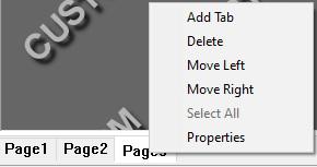
Custom report - copy page
Hi,
can you please consider to add an copy page function into custom report page/tab options to simplify work with new pages?
Doing copy with Ctrl+C of whole content from previous page and paste with Ctrl+V into new blank page doesn't keep formatting. Even doing this by group copy.
Require Tracker Field Checks on a scheduled basis, or at least notify Operator
Is there a way to force field checks on a schedule basis, otherwise the tracker will not measure? Or to at least send a forced notification?
File backup/restore from Trackers (Compensations, Probe/Tips)
1. If I comp a t-probe tip on one tracker, for a t-probe that will be used on multiple trackers, is there a way to upload that new tip definition to the other trackers through SFx?
2. Can we auto-export all calibration and compensation files to store on an offline server?
Kundesupport af UserEcho
