Hexagon Measurement SystemsNo matter what Hexagon measurement equipment or software you use, we want to hear your ideas and suggestions on how we can improve.
Thanks for your assistance in helping us shape the future. |
|


 Easier way to Dimension
Have an option to group features and dimensions in specific workgroup folders.
The best way I have seen this done is allowing the use of layers when dimensioning parts.
Example Layer 1 = top view ( this would contain all dimensions from top view )
Layer 2 = Side view ( this would contain all dimensions from the side view )
This could be done for both features and dimensions and you can easily pick and choose what features you want to have on the screen at any time. This is also good for grouping Datum features or critical features. I have used this on other CMM software's and works very well.


Quickly add shortcut items to toolbars
When navigating through drop down menus, give the ability to quickly add an item from that menu to the toolbar shortcuts with a hotkey or simple 'right-click' sub-menu choice would be much more efficient than customizing and searching through all the menus to find the item needed.

Evaluate profile of any line for a tube centerline
I have currently explored the options of being able to check profile of any line on a tube centerline using Hexagons software portfolio (PC-DMIS, TubeShaper, BendingStudio) but none offers a solution.
Currently, we are using a method that mimics the use of an Absolute Arm with a fork. We are probing the start
and end planes of the pipe and probes two 3D-circles at the start and end of each straight. Then we create
intersection points, bending radii (generic circles) and export this data for processing through an external
program (made by Hexagon Nordic) for evaluation of the profile of any line for the tube centerline.
If possible, I would like to have this natively in PC-DMIS, without the need for the external program.
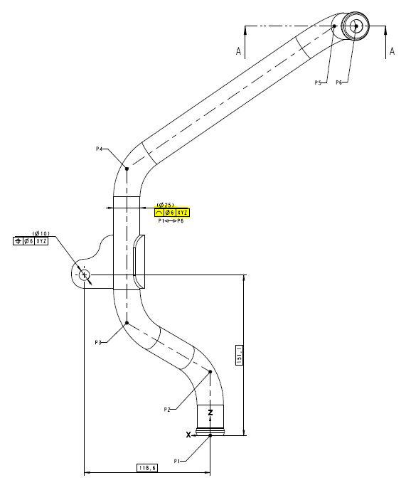
Disregard any GD&T errors on the drawing, it is the yellow marked tolerance that is of interest.
BendingStudio and TubeShaper are production-oriented software and not a "metrology" software thus
not dealing with this kind of tolerancing (but more LRA).
As far as I see it, this part of profile has been "left out" and is currently missing in PC-DMIS (and other
softwares?).

I would like the ability , while in the dimensional box, to be able to insert a note into the program
As I am programing dimensional features I would like the ability to hit the comment tab and enter a note before moving onto the next dimension. I have a costumer that wants all features numbered and those dimensions put into a report. I try to help the individual that fills out these reports by marking the number on the PCDMIS report page.

Auto cylinder/Cone ending offset should take into account current tip EWL
I have seen demo after demo on our demo block where the AE will setup a long stylus or some known not to fail ending offset, so that quick feature creating of cylinders or cones will not result in a path that would show stylus/probe collision. PCDMIS CAD and CAD++ do have the probe geometry and it is used for collision detection. Why can't PCDMIS auto feature cylinder/cone whether via toolbar or quickmeasure be smart enough to detect that the current ending offset (which works from CAD length back) might result in a stylus/probe collision for that specific feature and ask the user (graphically assisted) whether to override the current ending offset default?

Profile
I would like to output a profile without tolerances, and not be considered an OOS condition.

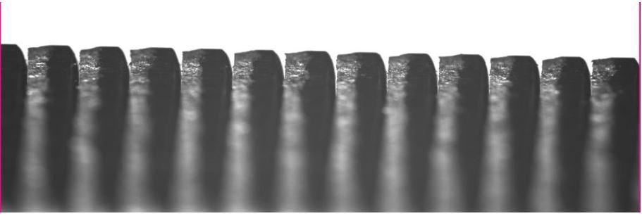
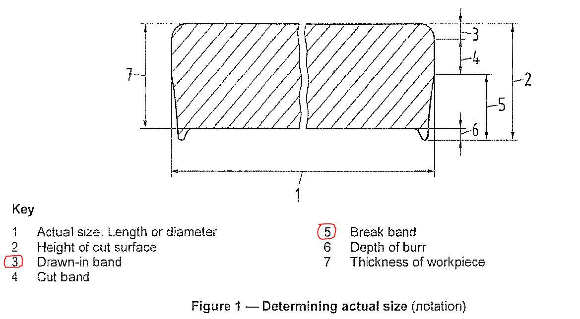
Morphological filter
Add morphological filter (filter that simulates use of bigger diameter ball for scanning) to scanned elements. It would be useful specially when measuring stamped parts. Because single laminas are usually partly cut and partly breaked small diameter ball styli is actually measures holes between laminas. See added picture of stamped stack and sketch from DIN 6930/2.

Tolleranze variabili
Avere la possibilità di inserire delle tolleranze variabili lungo la valutazione di profilo
Kundesupport af UserEcho
