Hexagon Measurement SystemsNo matter what Hexagon measurement equipment or software you use, we want to hear your ideas and suggestions on how we can improve.
Thanks for your assistance in helping us shape the future. |
|


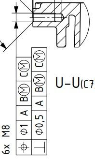
 Allow evaluation of angularity and perpendicularity vs 3 datums and MMC/LMC modifier to said datums with ISO1101 settings
Hi PC-DMIS team and users.
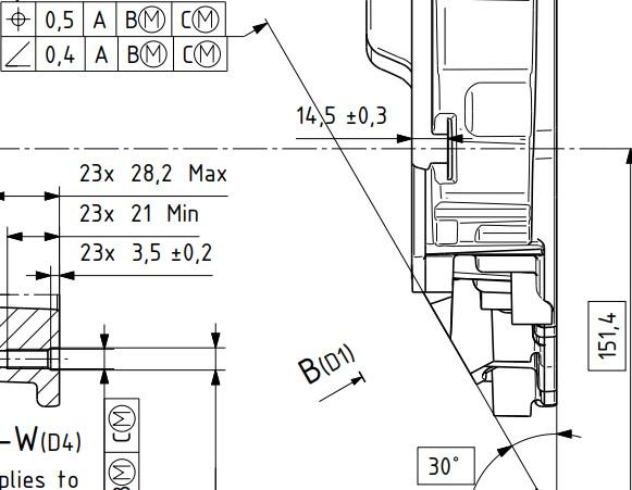
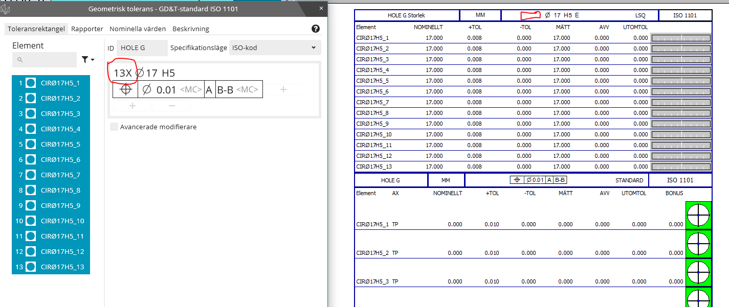
I have time to time encountered requirements that call out for angularity and perpendicularity versus 3 datums. Since PC-DMIS currently doesnt allow this, i have researched about it with my local PC-DMIS provider (Hexagon Sweden) and my employers ISO experts, who are part of the ISO committee. According to both Hexagon Sweden and the mentioned ISO experts, both perpendicularity and angularity, although not very clearly described in ISO1101 currently, are fully intended to be used with a complete datum system such as A B C, which is confirmed with the people who participated in writing the current version of ISO1101.
It is to my understanding that this would be equal to, or very similar atleast, to be using surface profile with a complete datum system but with the OZ modifier applied. This is my current workaround when i see such requirements on flat surfaces. But when the requirement applies to a bore
or a shaft, this workaround no longer works and i have no proper way to do it.
In addition to implementing a change like this, a yellow text warning, similar to the warning text to [DF] modifier could be used as soon as the 3rd datum is defined. Where the text implies that a 3rd datum for angularity and perpendicularity is not clearly described in ISO1101, and also asks the user to consider if this is really the intended requirement for the feature, or something along those lines.
In addition to this, bring back the ability to add the LMC and MMC modifier for the datums used for the angularity/perpendicularity evaluations. There is nothing stated that prohibits this in current standards. It is allowed for surface profile with OZ modifier, so after all, why shouldn't it be allowed to be used for angularity and perpendicularity.
If you need any further clarification or explanation, im happy to fill in. Thanks!
Below are 2 example pictures from the same technical drawing.


Add Length of Cylinder to the Measurement Strategy Editor and Quick Features Widget
I want to be able to set the length in the Measurement Strategy Editor as well as in the Quick Feature Widget. If the length was included when copying parameters, that would also be helpful. It just seems like cylinder length has been disregarded. We use a lot of cylinders for our hole locations, and sorry to say but the void detection still makes the probe go down too far and it rubs the bottom face. Our threads also do not go the full length of the drilled hole depth, so void detection just doesn't work too well for these features.

Summary mode
Bring back the summary mode of 2020 R2. You can keep the color scheme you have if you want. But not being able to hover the dimensions and seeing the results is very annoying. What even is the point of summary mode now??

Auto Features for Continuous Features (CF)
Allow a simple solution for creating auto features that per the current ASME standard are selected as continuous features (CF). I would recommend adding a CF button within the feature edit window to allow you to select the required features as well as a hotkey. To make it easier for the user the software should recognize what features are continuous.
This will help simplify the path optimization for Auto Features. Example: If you are measuring a continuous plane that has many interruptions you can now globally adjust the parameters and you don't have to construct a scan of all the individual features.
This would also be a good move since the popular metrology software Zone3 already has the ability to select multiple CAD surfaces as a CF.

Report template: When is it possible to insert the scan on the 3D CAD with the individual points (T-difference) also in the report as a 3D image with the deviations visible?
It is also possible to click on individual points and have the deviation displayed directly in the report.
Probe Transparency
Add an option to make the probe transparent in setup for all of your programs. This could also apply to other lighting settings as well.

Enable/Disable Clip Planes in Program
I'd like to be able to enable and disable clip planes within a program so that I can take live snapshots of profiles in the middle of parts without having to keep clip planes on at all times. This could be added in to the viewset feature as well.

关于替换元素名称
在2018版本甚至以前的版本 替换元素名称可以在概要模式下进行,并且替换名称之后测量误差还在。更新2022和2023以后替换元素名称不能在概要模式下进行了,即便更换为命令模式替换元素名称之后 误差值不在了。

Work with Sample Hits
As a programmer, I would appreciate the ability to work with Sample Hits from Auto Features in the new versions.
In the picture is an example of usage.
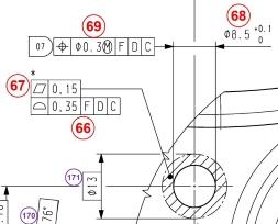
I need to use at least three Sample Hits to measure the hole precisely.
Then I have to measure the contact surface around the hole, e.g. as an Auto Feature "Auto Plane" using "Relative to" to this hole.
If there was a possibility to use Sample Hits in the construction, I would measure the hole with using more Sample Hits which I would then use to construct the contact area around the hole and I would save one feature measurement in the program, which itself is not much, but if you have e.g. ten such holes on the part, it already saves some time spent on the 3D machine, which is very welcome in serial production.
Servicio de atención al cliente por UserEcho
