Hexagon Measurement SystemsNo matter what Hexagon measurement equipment or software you use, we want to hear your ideas and suggestions on how we can improve.
Thanks for your assistance in helping us shape the future. |
|

 Add the ability to delete or transform multiple CAD assemblies and one time.
Under CAD assemblies, I would like to be able to select multiple assemblies, to either delete, or even transform. As it is I have to select one at a time. When using 30+ assemblies it can take sometime to transform or delete.

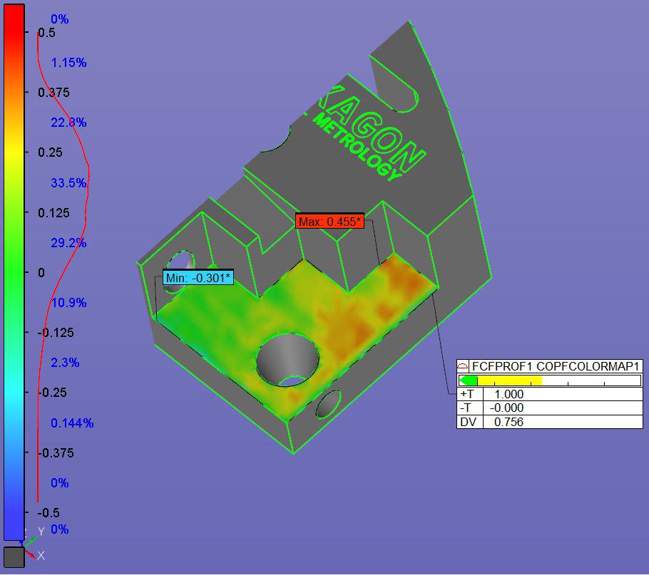
 Min / Max point on colormap
Min / Max point on colormap is not representative to surface.
This point will "nearly" always be on the surface edge!
And this value is used when you evaluate Profile surface dimension.
If you take a look at pictures below and special on the colormap / colormap scale. 99 percent of this surface is green and orange. The Profile surface dimension value should be around 0.5 but it is 0.756 (ASME).
This because of what I believe error from the scanner.
Different ways to solve this could be:
Let the Min / Max be on a colormap "area" and not as a point.
Or an outlier filter...

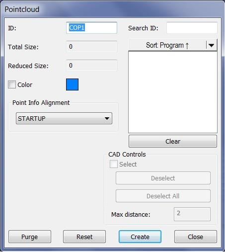
 New Pointcloud window with CAD Controls
Ability to scan only select/selected CAD Surface with tolerance (Max distance).
New window :-)


 Out of tolerance first/Out of tolerance last
Everyone knows the Report Template TEXTANDCAD_OOT.RPT
A lot of my customers ask me for a report template which add the OOT dimensions first in the report or last in the report.I made a template for them but it will be nice to be added as a default in report window.What do you think?

 graphic display window flagged note / comment
add flagged note / comment text box in graphic display window.
for adding part, assembly, job, numbers or other instructions as desired.

 Add (M) to the concentricity/coaxiality FCF builder
ISO allows for the (M) modifier on concentricity and coaxiality, but I have yet to see this added to PC-DMIS. In order for my conc/coax evaluations to comply with the drawing, I must either do a bonus calculation, then an conc/coax evaluation with the calculated tolerance - or, use position to evaluate the conc/coax where the (M) modifier can be used.

 Report Window
Please look into adding the ability to move/view the report window on a second monitor.

 Can we make the Ser Number field "Text Only".
Currently a Serial Number like 123-456 will be read as -333. I understand that I can add an underscore, but doesn't it just make sense to allow the serial number to be entered as it appears on the part?

 Tools for cleaning up the Recent Files, and viewing the complete path
It would be nice to be able to easily remove files from the Recent Files list, for example by right clicking and getting a menu [Remove This, Remove Non-existing, Remove All].
It would also be good to be able to see the full path of a recent file, for example as a tool tip when hovering with the mouse.
(none of the existing Categories match - maybe add User Interface to the Categories?)
خدمة دعم العملاء من خلال UserEcho


