+5
Show constrained degrees of freedom in the geometric tolerance dialog window
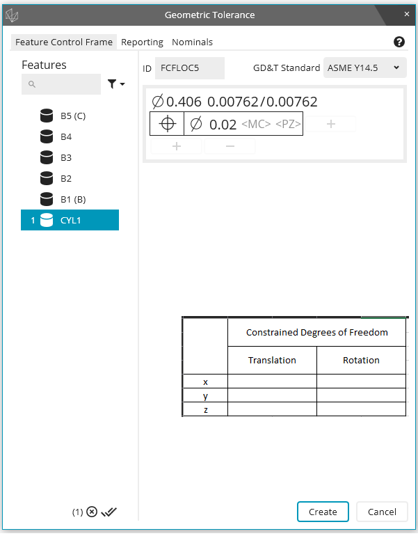
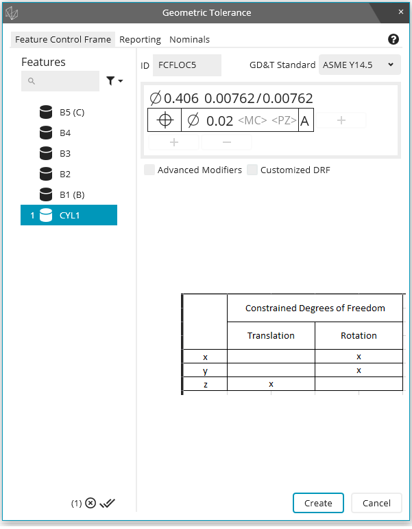
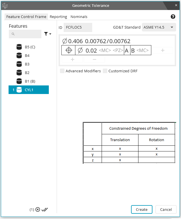
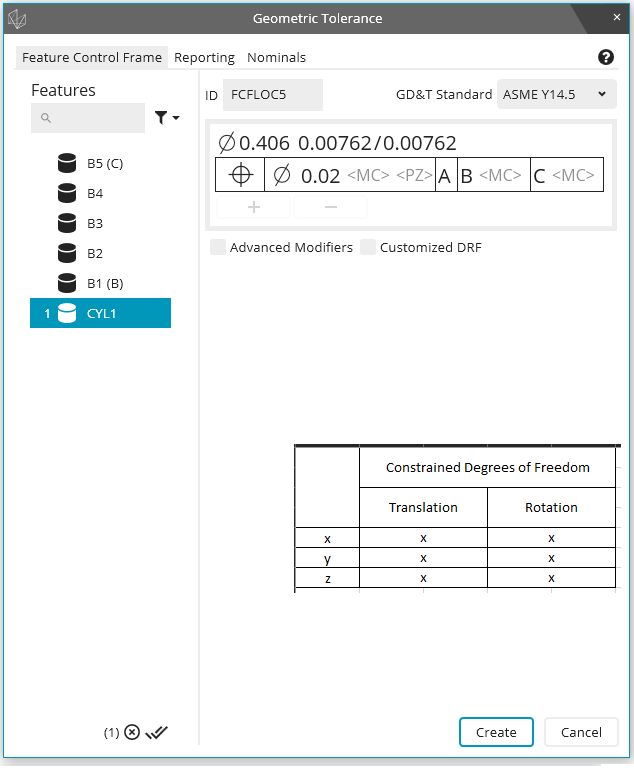
It would be helpful to see the actively constrained degrees of freedom as the feature control frame is being built in the geometric tolerance dialog window. As an example, assume I have a primary datum plane (normal Z+), a secondary datum cylinder (axis along Z), and a tertiary datum cylinder (axis along Z). Then, as I build my feature control frame, the geometric tolerance dialog window shows me which degrees of freedom become constrained as the images below show:


Service d'assistance aux clients par UserEcho


You used to see it on the report if there was a rotation, but with the latest versions you don't see it so you don't get any warning at all.
This is a great idea!
Thanks Wes, you can vote on my other topic here if you'd like to bring back a representation of datum shift: https://ideacenter.hexagonmi.com/communities/40/topics/942-2020-r2-datum-shift-reporting
If you mark the "customized DRF" check-box, you can see which degrees of freedom each datum constrains
Thanks Neil. I know you can see the degrees of freedom that each datum constrains when activating the Customized DRF checkbox, but most of the time people don't use a customized DRF. My idea was more dynamic in that the dialog window would show constrained DOF "real-time" as the datums are selected. The Geometric Tolerance command doesn't allow for material modifiers when choosing a Customized DRF, so the DOF constrained may become a bit blurry when modifiers are used. It may be a bit difficult to define at this point, but I thought it might be a helpful option for newer users.