Hexagon Measurement SystemsNo matter what Hexagon measurement equipment or software you use, we want to hear your ideas and suggestions on how we can improve.
Thanks for your assistance in helping us shape the future. |
|

 Please change it back. When I color a cad model, I have to color one feature at a time or else hold down the ctrl key to color multiple features. Please fix it back the wat it used to be.

 Find Hole parameter setting description clarity for Check percentage.
The Find hole parameter settings was not well described in PC-DMIS and should have been corrected years ago for better clarity of the meaning for the setting.
With Summary mode in 2019R1 will show that the second parameter is for the Find Hole. (This view feature in Summary Mode is no longer available in the newer versions.)
Within the Settings dialog window the only value for Check is for distance not for the Find Hole.
Then the Parameter Settings will show Check percent with no description. Leave one thinking that this could be for the Check distance.
As an example Check percentage should have been described as (Check Find Hole percent)
CHECK/1,0.1 (First parameter is for Check Distance and Second parameter is for Check Percent for Find Hole.)
Help Menu:
The Check Distance box defines the distance past the theoretical hit location that the machine continues to search or check for the surface of the part. This distance is after it traverses the Prehit Distance value. The default value is zero.
The Check Percent value determines the percent of the total distance moved when performing a Find Hole operation. Be aware that if you type 1, the value is equal to 100 percent. Thus, 100% would be entered as 1, 25% would be entered as .25, and 10% would be .10.

 more info in color map annotations
to créate big reports with new function " capture", i think could be Good idea the possibility to add to annotation in the color mapping more info, not only 3D deviation.
maybe, right click add, nominal, measuered and tolerances, and change also the label by default.

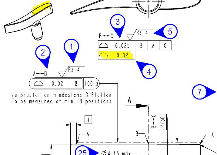
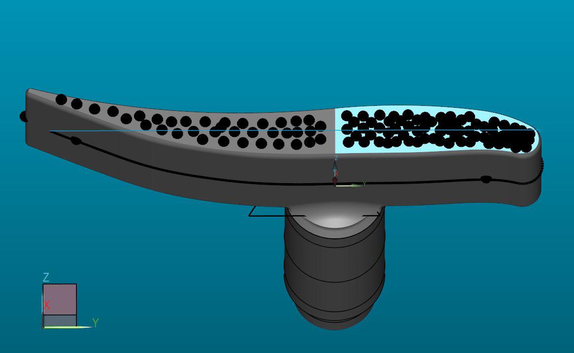
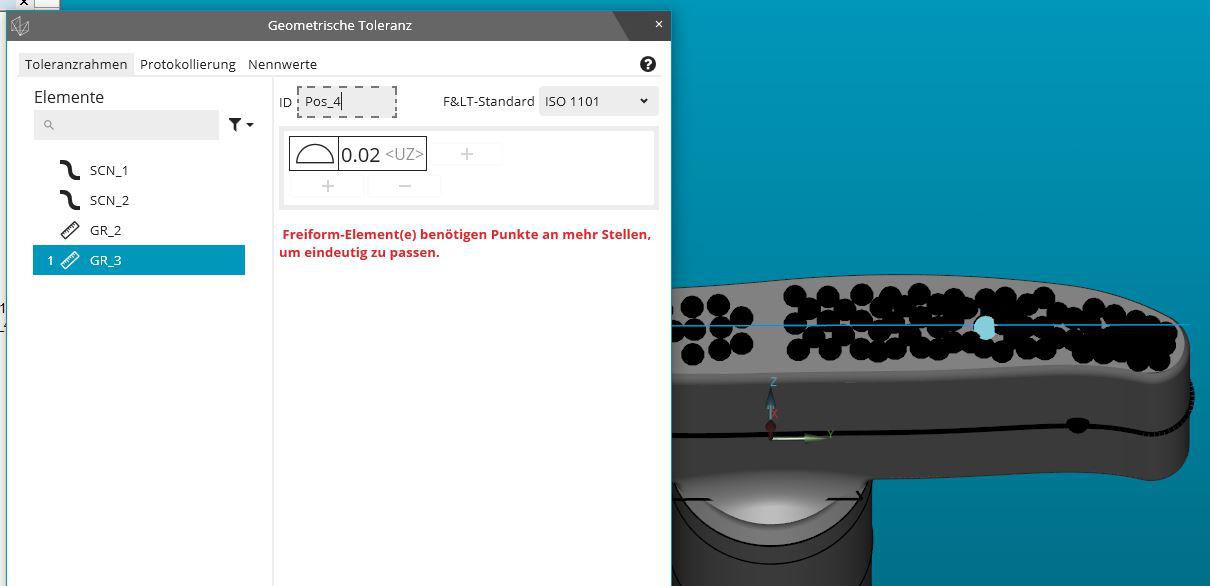
 PC-DMIS 2020R2 does not recognice a small free-form surface for evaluation
Subject Ticket 00253352.
PC-DMIS 2020R2 does not recognize a small free-form surface. The element group created is recognized by PC-DMIS as a line and can therefore only be evaluated as a line shape.
In version 2020R1, this free-form surface was still recognized as a surface.
Please ask for correction of this problem.


 Turn CAD Assembly Items on and off with code
If a program has part of an assembly being measured for the sake of an alignment and then you need to add a part to measure what you need, or to show deviation before and after assembly. Use code to turn model items on or off as the program is executing.

 Leitz Senmation / PC-DMIS compatability
Why cant PC-DMIS control all of the senmation options? I should not need quindos . it puts a burden on the ability to stay with Leitz when I need more options. ZEISS runs all of theirs seamlessly in Calypso..I want my Leitz to do that!!

 Rounded Polygon Auto Feature
Auto Features should include Rounded Polygons, called "Stoffel Polygon" . They are generated by plotting through an equation. would be nice to be able to find some inspection dimensions from it. See Machinist Handbook.

 WINDOW / TEXT RESIZING FOR ALL FEATURE DIALOGUES
Every pop up window should be resizable and allow for increased text size for easier viewing. Ergonomics should always be a priority....

 PROBE LIST SCROLL BAR FOR PROBE CHANGER
There should be a scroll bar for the probe list drop down in the Probe Rack, when adding or changing what is in a port.
I have asked for this in the past...should have been there from the beginning.
Service d'assistance aux clients par UserEcho


