Hexagon Measurement SystemsNo matter what Hexagon measurement equipment or software you use, we want to hear your ideas and suggestions on how we can improve.
Thanks for your assistance in helping us shape the future. |
|


 create assemblies with mating parts instead of coordinates
By using CAD models, mate parts together the way Solidworks does. It has the ability to click mating center points to lock the XY and the click two mating faces to lock the Z. This would make it easier instead of inputting a XYZ coordinate move.
Require Tracker Field Checks on a scheduled basis, or at least notify Operator
Is there a way to force field checks on a schedule basis, otherwise the tracker will not measure? Or to at least send a forced notification?
File backup/restore from Trackers (Compensations, Probe/Tips)
1. If I comp a t-probe tip on one tracker, for a t-probe that will be used on multiple trackers, is there a way to upload that new tip definition to the other trackers through SFx?
2. Can we auto-export all calibration and compensation files to store on an offline server?

Adding the per unit flatness to a variable assignment.
This would help users with legacy dimensioning to capture the Per Unit answer and send to stats.

Kindly share in video how to use leap frog alignment when using Romer Arm portable machine

Making network licensing available
It would be nice to use the software on multiple pcs and "check out" license as needed. I do this with many other types of software and it works great. I'm shocked Hexagon does not utilize this. The license can be parked on my server and be accessed by multiple PC's only allowing the paid number of licenses to login. I'm being told this isn't available for PC DMIS from Hexagon.

Build a color map of a measured part in comparison with another measured part pattern but not with CAD
It would be great to be able to build a color map of a measured part based on its comparison with another patter-part and no with its CAD.
This option would be very usefull, for example, in the case where we have 2 parts: at first sight both of the parts have the same dimensions because the results of the measurements of both parts with caliper are similar and both parts are on tolerance with the CAD/drawing, but only one of them could be assembled. So, it would have sense that the difference between them must be on the shape, and the mentioned option would be the best chance to be able to see it.

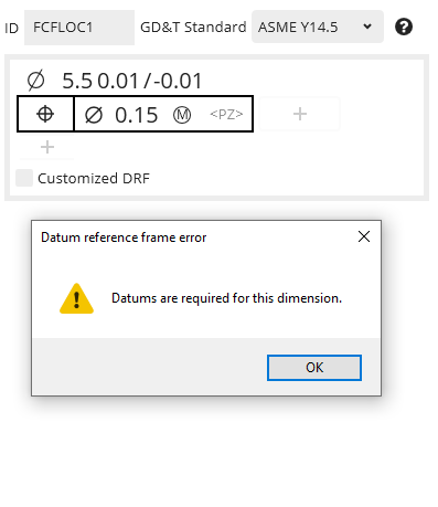
Position to No Datums
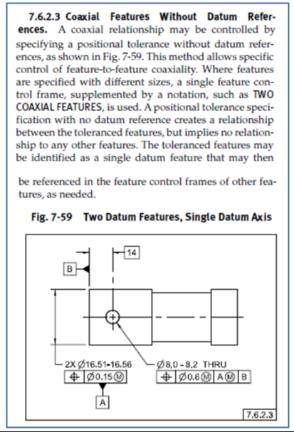
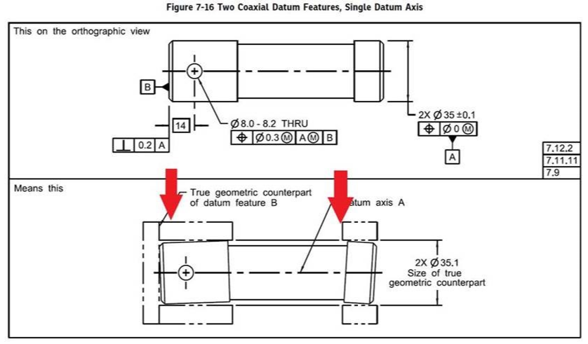
ASME Y14.5-2009 7.6.2.3 Coaxial Features Without Datum References
This is an ability that I would like to see in PC-DMIS Xact-Measure.
If the call out is per the spec then PC-DMIS should abide by the standard.

concentricity and coaxiality - References "A-B"
Why can't I use the "A-B" cover for concentricity and coaxiality?
References are circles and cylinders.
Searchable features in ClearanceCube Definition Status Tab
I'd like to be able to search for a given feature in the ClearanceCube Definition Status Tab. Scrolling thru a mile long list is not fun. In an ideal world, if the Clearance Cube Definition Status tab was open clicking on a feature label in the graphics window would take you to the feature in the Status tab.
Customer support service by UserEcho
