Hexagon Measurement SystemsNo matter what Hexagon measurement equipment or software you use, we want to hear your ideas and suggestions on how we can improve.
Thanks for your assistance in helping us shape the future. |
|


 Having the option to select a variable as a lighting option instead of a percentage in lighting parameters
For example, in vision, you save lighting settings to percentages you want. I would like to have a setting where I can pick a lighting that I want on with a preset variable. Like Bottom Light = V999. Then the programmer can assign the variable at the top of the program.
So instead of it saying "Bottom Light=<off, 100, on>" it would say "Bottom Light=<off,V999, on>"
Instead of having to manually type this for every feature, it will hold the value as a variable rather than a number. This could potentially solve all lighting issues going forward and make it super easy for a programmer to update/change programs if needed. And if possible

Add a dropdown menu for the contruct feature window
Ad a drop down menu in the construct feature window to select what kind of feature you want to construct.
This makes constructing different feature's easier, and faster.
The function i'm looking for is already in place with the auto feature window, here you could start with a vector point, and then select the drop down menu to change to cylinder.

Add due date minders for SMA and CMM maintenance
Add a due date minder for SMA ,and add a due date minder for CMM maintenance.
For example, PC-DMIS pop-ups a prompt to remind the operators that the SMA will expire in 3 months...
because this is closer correlated with measuring application.

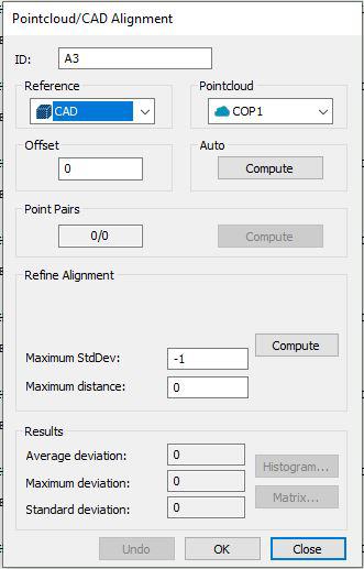
"Manual" Alignment of Pointcloud
It would be nice to have the opportunity to manually (by using mouse) align pointcloud to cad model, or one pointcloud to other pointcloud and from here make eventualy refine alignment. Idea is to put with mouse COP on CAD or other COP to lock this on specific area.Thanks to this it would be easier to align only partly scanned surfaces. Today even if I using point pairs sometimes alignment is moving far away from expected place. Actual functionality is working good only if whole part is scanned allround.


Show pdf file location in print command
Printer PDF file location is hidden in editor window. File saving locations should be highly visible.

Add a calculator function to several menus
Add a button to several menu's that expands a calculator and assign a hot key to open/close the calculator.
Suggested Locations:
-AutoFeature Menu
-Constructed Feature Menu
-Alignment Menu
-Pattern Menu
-Transformation Menu
-Clip Plane Menu
Huge plus if the calculator had some intuitive dynamic functions.
Color coded edge point preview
Much like the auto-circle it would be intuitive to have the same color coding on the path lines for edge points.
Currently, auto-circle's first hit is purple and last is orange.
It could also be useful to have say an arrow head or something noticeable for sample hits.
Most of us probably have the orders memorized, but its more intuitive to color code and easier to train with visuals.
When Installing PC-DMIS Check the Locale or Ask user if they wish to work to ASME or ISO standard
When we install PC-DMIS Check the Locale or Ask user if they wish to work to ASME or ISO standard as default so the registry key is then set correctly. By default it is set to ASME, but users working to ISO then have to change the Standard each time using Xactmeasure. The situation is worse for legacy as they might be reporting profile tolerance incorrectly without there knowledge. Most users are not aware of the registry key USEISOCALCULATIONS and even if they do they might not have permissions to change it. We should be more active to ensure users are using the right applicable standard at install time.
Сервис поддержки клиентов работает на платформе UserEcho
