Hexagon Measurement SystemsNo matter what Hexagon measurement equipment or software you use, we want to hear your ideas and suggestions on how we can improve.
Thanks for your assistance in helping us shape the future. |
|

 Alphabetize Report Option
I would like an option to alphabetize inspection reports. I typically inspect parts to a ballooned drawing. I resort to saving all my dimensions until the end of my program and name them BALLOON1, BALLOON2, etc. The problem is when I have a part with hundreds of balloons, I'm hopping around from alignment to alignment and workplane to workplane. It would save time if I could create the dimensions as I'm creating features so that I'm recalling alignments and switching workplanes less often.

 Shape options for clearance
Clearance cube works well for square/rectangle parts but not ideal for cylindrical shaped parts. A clearance cylinder would work well for round parts that have features i.e. circles etc... on the outer perimeter of the cylinder.

 Auto Element Kreis Scan auch mit Stützpunkte/ Auto element circle scan also with support points
Mein Idee beinhaltet dass beim Auto Element Kreis Scan auch Stützpunkten möglich sind.
Aktuell ist dies nicht möglich.
My idea is to program the scan with the auto element circle also with interpolation points.
Currently this is not possible.

 Let some settings/files be stored on a network for shared settings
Let PC-DMIS store some setting/files on a network so they can be accessed from different machines / PC-DMIS installations.
I'm talking about settings/files like:
- usrprobe.dat
- MaterialCoefficients.xml
- xxx.MSExml (StrategyEditor)
- MessageBoxOptions.dat
- The User Interface (Icons and so on)
- Colors of the edit window
- Colors of the features
- and many more
Having many machines and many pc-dmis installs is a pain to maintain which costs hours.
Having a central settings directory on the network would save a lot of time.

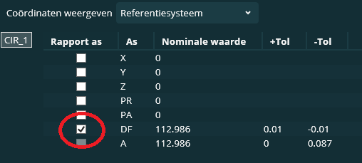
 Enable DF value automatically off in settings
When programming True Location dimensions (FCFLOC), i would really love to turn off the DF (diameter) setting by default instead of turning it off at every instance.
This could be a setting in the settings list at the (F5) settings editor.

 scan set- profile surface dimension- graph=on will show surfaces highlighted in addition to point arrows
it would be nice to either manually assign, or automatically attach, surfaces in a scan set that can be displayed graphically when analyzing a scan set. sometimes when scan sets are dense the arrows make it easy to see the deviation, but the actual surfaces that are measured/not measured can be more difficult to determine. Could the surfaces also be highlighted as shown in the attachment? Presentation1.pdf

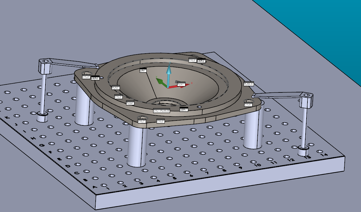
 clearance cube - Selection solid vs jigs
The idea is to make the setup on ''solidworks'' and import all the assembly and after select the part to inspect.
the goal is to make a colision detection with the jigs and correct move point to avoid collision.
thanks

 Easy access to axis data of geometric tolerance commands
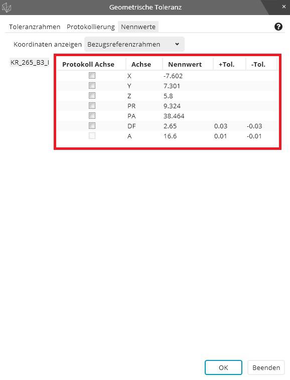
Make it easy for the user to have access to all axis data inside the geometric tolerance command via variables.
We used to have the option to write "FCFLOC1.X.MEAS" while this syntax still works it only works if just one feature is selected inside the geometric tolerance command.
The new syntax is "FCFLOC1.SEGMENT[1].FEATURE[1].MEAS" while we can change the feature number to get the different measurement values there is no possibility to get the axis data of the features.
My proposal is to let the user add the axis letter(s) before the ".MEAS" or ".DEV" to indicate which axis he wants extracted. If no letter is indicated the syntax behaves as before.
The syntax should work with all available axis letters not only the ones shown on the report.
Examples:
"FCFLOC1.SEGMENT[1].FEATURE[2].X.MEAS"
"FCFLOC2.SEGMENT[1].FEATURE[5].Y.DEV"
"FCFLOC3.SEGMENT[1].FEATURE[3].PA.DEV"

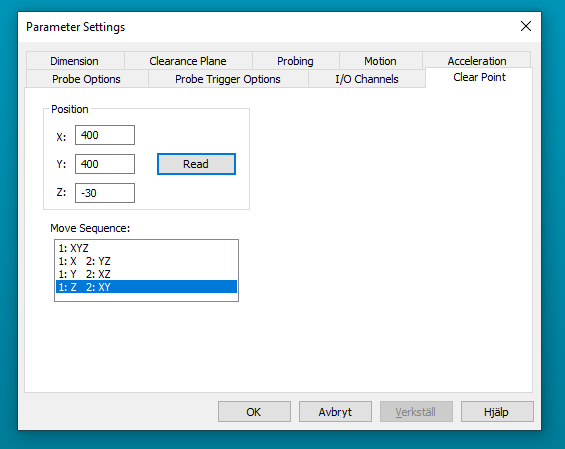
 Ability ta add multiple clear points
It would be good to have the ability to add multiple clear points and to configure them individually regarding the axis movement order.

 Backwards compatability with Xact
Want backwards compatibility with Xact measure for GD&T. I have hundreds of programs that would need to be reviewed. I'm in a regulated industry and can just imagine the chaos that would happen with changing to the new scheme. I appreciate the effort and improvements in the update to the new scheme. However, the costs and headaches involved in ensuring that older programs will provide the same results are going to hold us back. I have gotten around updating previous release updates by arguing that the changes are relatively minor and are mainly programming aids. This is a major change.
Other alternative would be a way to not allow Xact measurement routines to not run at all.
Late to the party and realize it's probably not possible but still....
Сервис поддержки клиентов работает на платформе UserEcho
