Hexagon Measurement SystemsNo matter what Hexagon measurement equipment or software you use, we want to hear your ideas and suggestions on how we can improve.
Thanks for your assistance in helping us shape the future. |
|

 Distance-to-go while executing a program
When executing a program, not much information is available to you, and knowing how far a probe is about to travel is a great indicator of whether or not you're in the right ballpark.
Simply a value showing how far the probe is going to move before it reaches the point in which it will switch to touch speed or begin moving in another direction.
We see more and more machinist being trained to run PC-DMIS, and this is a comfortable feature they're used to seeing when running their CNC machines. I think it could help prevent many CMM crashes.

 enhance search function for groups
Problem:
The group function is often used to keep the routine tidy and organized.
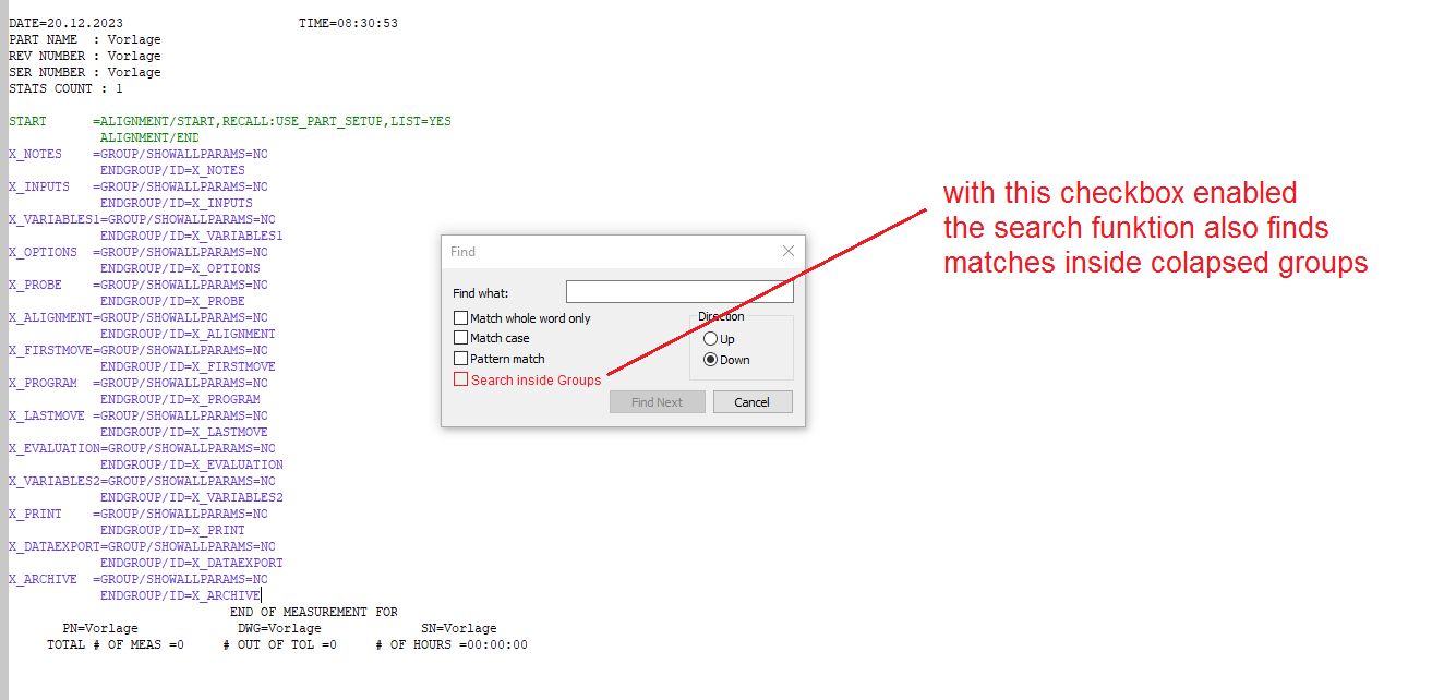
But when you have "collapsed" groups in your measurement routine, the search function doesn't show matches inside of them. The user needs to open all groups first to use the search.
This is very time-consuming. Inexperienced users may not know that they have to open the groups first.
Solution:
Add a checkbox to the search function called "Search inside groups" or similar.
When checked, the search function also looks inside groups for matches.

 Zoom on initialization Optiv
On initialization of the Optic measuring device, the camera is always zoomed completely on maximum zoom.
This makes it hard to find my piece. I first need to zoom out completely, before I can start.
For me, I prefer to start with zoom on minimum, but maybe someone likes to start with zoom on maximum.
Can there be an update where we can have that choice?

 editing location of dialog boxes
Allow editing location of dialog boxes from within PCDMIS rather than only from the settings editor. Or at least make a button to bring them to center of screen. EX: operator moved the execution dialog box off the screen by accident, the only way to correct this is to go into the setting editor and manually change the location.

 PC-DMIS - Fix CAD Vectors automatically when importing CAD models
PC-DMIS - Fix CAD Vectors automatically when importing CAD models
As per Edit | Graphic Display Window | CAD Vectors | Fix CAD Vectors

 More editing possibilities for ClearanceCube
As a programmer I would appreciate more options in the ClearanceCube settings.
We load 3D data into the programs in coordinate systems as we receive them from the customer. This is due to future changes in the 3D data. If the 3D data is not in the "ideal" coordinate system, we have no way to fit the ClearanceCube as we would like.
Here is an example of such a problem:
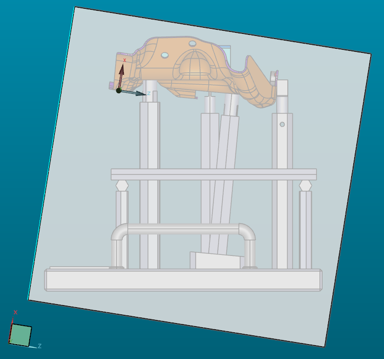
It is clear that I can hard modify the 3D data to get it into the "ideal" coordinate system, but that would mean doing it every time a customer sends me a new version of the 3D data, and that is not the best way to go.

 Improve changing the datums in GD&T command
When changing a datum of a GD&T command from the command-view the subsequent datums get deleted.
This should get improved. So I can change the middle datum without the last being removed.
Example:
I have the datum system |A|B|C| I want to change it to |A|M|C|
The second I change the |B| to an |M| in the command-view the |C| gets deleted and I only get a |A|M|

 Auto Element Kreis auch mit Teil-Segmente wie an der Optiv (Punkte Auswahl Messbereich) /Auto element circle also with partial segments as at the Optiv (points selection measuring range)
Meine Idee wäre es bei Auto Element Kreis auch mit Teilsegmenten wie an der Optiv zu arbeiten (Punkte Auswahl Messbereich). Somit könnte man Messbereiche einfügen und separat definieren.
Meine Idee wäre, mit Auto Element Circle auch mit Teilsegmenten wie beim Optiv (Punkteauswahl Messbereich) zu arbeiten. So könnte man Messbereiche einfügen und separat definieren.
Customer support service by UserEcho
