Hexagon Measurement SystemsNo matter what Hexagon measurement equipment or software you use, we want to hear your ideas and suggestions on how we can improve.
Thanks for your assistance in helping us shape the future. |
|

 Copy ABC paste CBA
In the edit window, I would like to be able to copy a set of elements ordered as A-B-C-D and paste them as D-C-B-A.

 MACHINE 3D MODEL DETAILS
Would like to see and use the threaded holes of the tables, for fixture position and at the same time then we can see where machine can reach.

 add Cad selection option to COPOPER filter distance tool
We would like to be able to filter different areas with different densities.

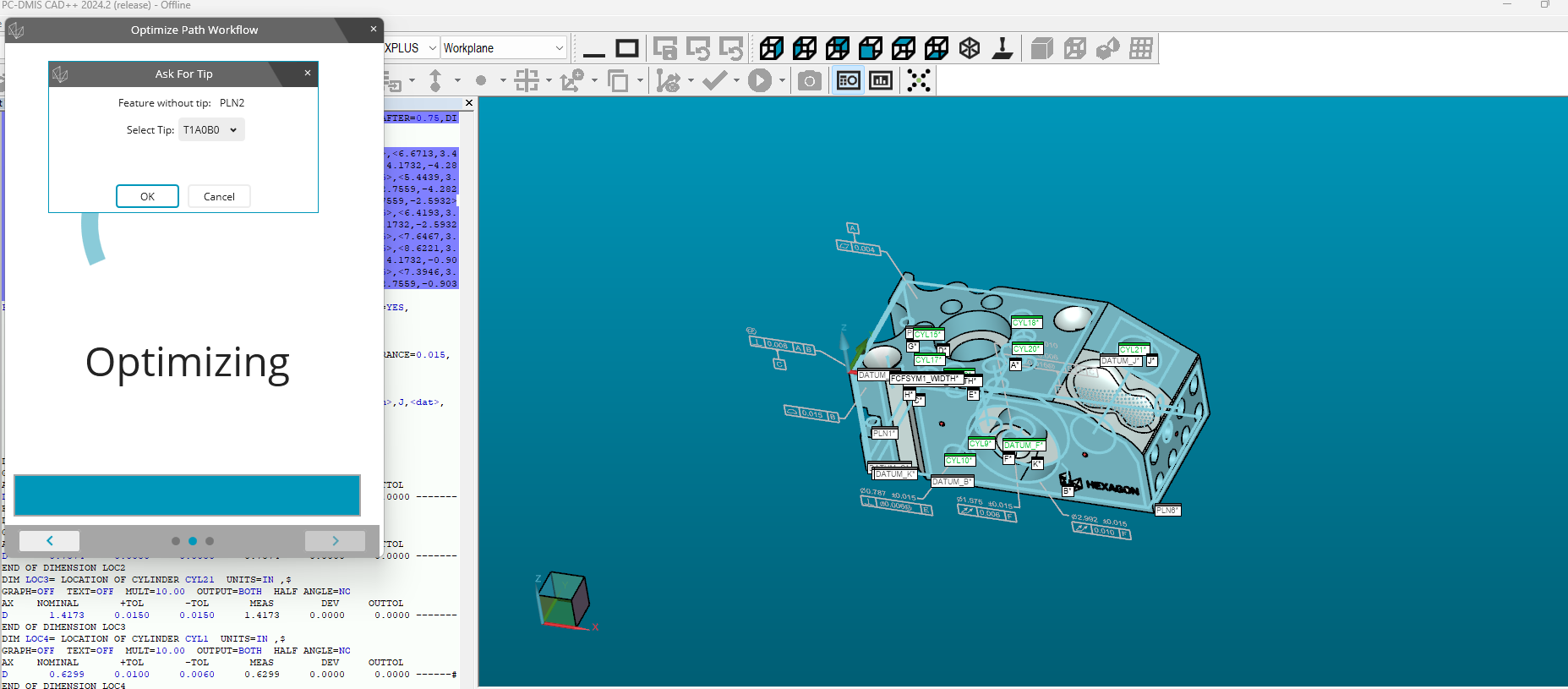
 Allow for the 3d Model to be rotated and move the labels around while optimizing path workflow

While creating a new test program using the QIF model, I had to edit the program and enter different tip angles to measure features on different planes / axis directions. But while the Optimize path workflow is active and the "Ask For Tip" window is open to select the tip angle for the applicable feature, the model CAN NOT be rotated or moved to get a view where this feature is and make a choice on the tip angle, I also can't move the feature labels or hide them for clarity in the Graphics window.

 Report spacing
Many years ago i remember changing a setting in the settings editor that would add a space between the dimensions on the report. I cannot remember where this was. Currently, we insert a blank report comment to get the space in between. Does anyone know if this option still exists?

 Marking tips in probe utility window that you recently calibrated
It would be nice to have some kind of identifier next to tips in the probe utility window that you recently calibrated. It would make it so much easier to keep track of what and what I did not calibrate. Something like the notification dots used on smart phones

 Adding a built in goto label into a preheader and end of program
As Header states, a simple built in label at the end of the program and at a pre header beginning would be very helpful to allow header label modification, easily start over program based on conditional statements, or end program.

 Option for saving exclusion planes.
I think an actual option for saving exclusion planes to be used in other routines would be extremely beneficial and would simplify things.

 Suggestion for a filter for laser COP
One filter that I really wish was available for a laser-scan COP is a one that just removes all laser points within x distance of a seam in a solid model. Trying to get a surface profile measurement of a scanned part is inevitably thrown off because the physical part has had the edges smoothed per drawing requirements, but the model had sharp edges so it shows up as an out-of-tolerance condition.
I'd love to have a filter were I can specify a distance, and then either select individual seam lines or just pick "all seams" to filter out these edge points from the COP.
A .015"/.005" break edge requirement means on a .010-profile surface all of the edges will be out of spec, and the measurement will not be an accurate representation of the part.
Servicio de atención al cliente por UserEcho


