Hexagon Measurement SystemsNo matter what Hexagon measurement equipment or software you use, we want to hear your ideas and suggestions on how we can improve.
Thanks for your assistance in helping us shape the future. |
|


 Change of name
Hello, is it possible to create a script which allows to modify all the names in PC-DMIS. For example for a PLN element in PL or CIR in CER as well as the geometric tolerances.

Probe Weight warning
Have a warning when the probe that is being built in Probe Utilities may be too long/ heavy for the specified module to calibrate accurately. This would prevent investing the time in an OFFLINE program that will have issues due to the probe build that is specified. Probably needed for both touch and scanning probes. Just need the warning, probably multiple times, don't want PC DMIS to outright refuse the probe build, especially on a marginal case. Just burnt myself with this..... :(

Report only maximum formdeviation from multiple features
When on a cilinder a circularity is asked, it has to be circular in every cross section. So you need to measure multiple circles.
When you dimension the circularity you need to sele3ct them all, and then it will report all the circularities.
It is possible that you get the option to only report the maximum?
This is also applicable to straightness.

Feature used/unused - Check tool
I would like to have a tool - function that can check witch feature are used in program (construction, dimension...) and witch are not and can be deleted to shorten the program. Also which constructions have been broken because the features have been deleted and can also be delated.
I miss the tool that would help me clean the program after changing it.

customized DRF
Hi,
It would be great than the True Position Customized DRF working in any direction. ( Show the right x,y,z,u,v,w)
The help contain :"PC-DMIS requires that the primary datum feature be leveled to Z+, and the secondary datum feature be rotated to X+. "
Now it only works according to the help, but why can't the primary basis Yminus the rotateX minus, for example.
Now I need a datum A [y, u, w] B [x, v] C [z] but it is not possible to show on report.
What the pcdmis displayed A[z,u,v] B [y,w] C [x]
Unfortunately there is always extra time to create different rated, current elements and test whether PcDmis calculates well what we want ...
In this case, it displays wrong but the calculations right. We suggest to develop it.
Thanks!

Geotol Profile with Pointclouds
I'd like the ability to use Geotol Profile with Pointcloud data. We can currently use legacy profile with pointcloud colormap data. We need the same with GeoTol.

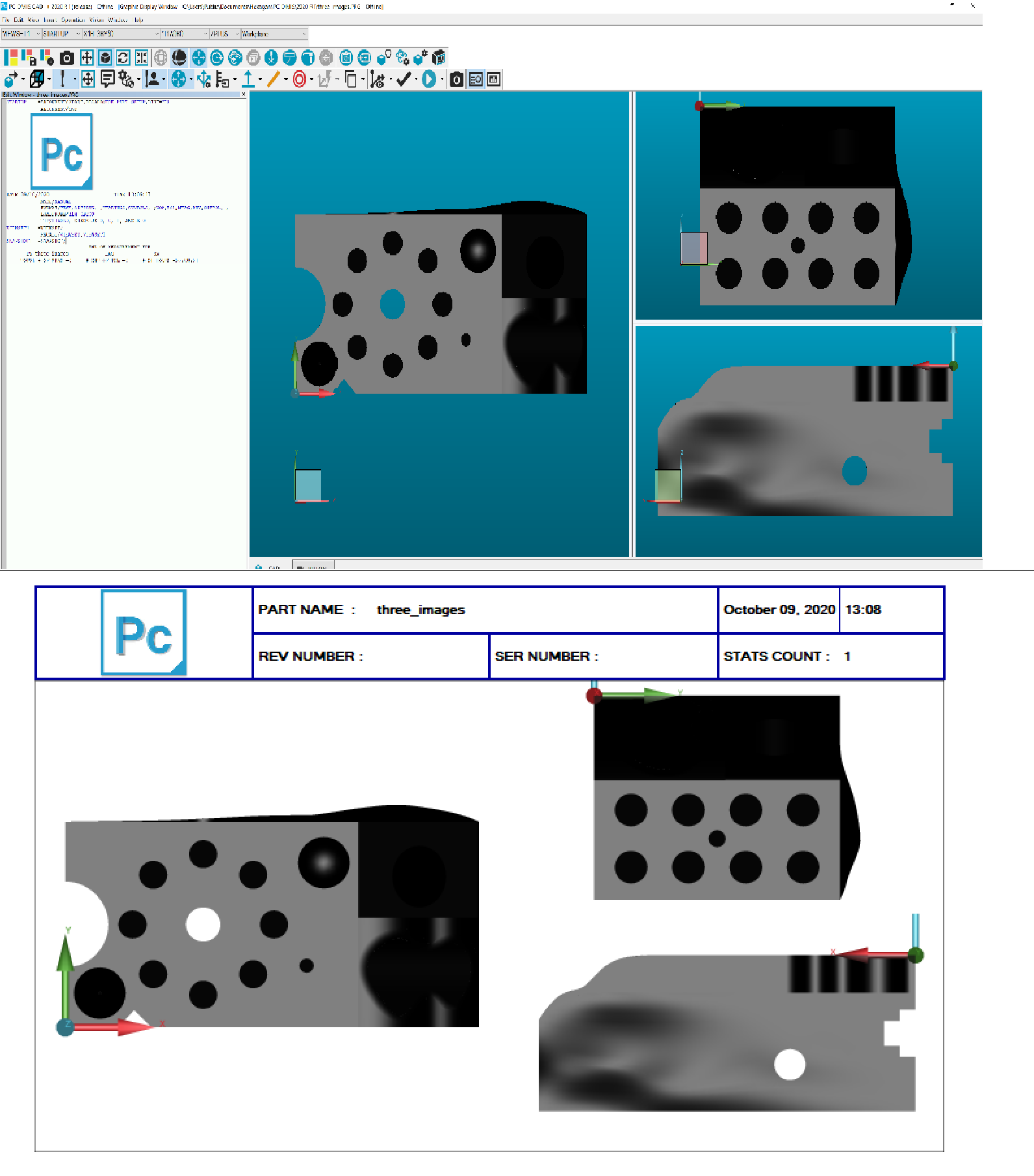
3 different cad views
Is it possible to display Cad x, y and z in one page on (report page?) so using 3 images in one page
I want to see the cad image of 3 dimensions and the size label. such a report format should come loaded on pc dmis.
To be able to not have recents show up on home page
Reason being if im on offline and make a change to the program and an operator on the cmm opens through the recents it opens an old file not the new one with changes.

Customer support service by UserEcho
