Hexagon Measurement SystemsNo matter what Hexagon measurement equipment or software you use, we want to hear your ideas and suggestions on how we can improve.
Thanks for your assistance in helping us shape the future. |
|


 More Vision Algorithms
I've seen competing software that has no problem with edges I have problems with in PC°DMIS.
Whenever I'm on a vision project, I always struggle to get edge parameters correct until lots of trial.
Nearest Nominal and Matching Edge are sometimes very amazing and work quite well, but often there are program parameters and changes that are not feasible with those tools (at least not with out lots of work, meaning if I quote for the struggle I lose the work anyway).
Can we develop a plan for implementing better algorithms? I can, and possibly the rest of the community, can submit difficult tasks to measure and submit them for review.
Program Icon changes with Version
Change the ICON of a program in the explorer window depending on the version it is saved in.
Example:
-2018 R1 & 2 Icon would be the number 18
-2017 R1 & 2 icon would be the number 17
etc..
We have multiple customers that require different versions of PCDMIS - before we send the program we have to verify that it is in the correct format. This would be a quick visual to verify that it has been saved correctly.
Conditional Group Controls
PC°Dmis has a group command.
It would be nice if it were possible to check conditions inside of the group command and then the group command would output a conditional variable.
Example:
I place all of my critical feature dimensions inside of a group command. I then set the conditional statement for:
-any out of tolerance condition inside group = to 1
-any % of tolerance condition inside group = to -1
This condition is written to an external record (comma separated)
I can now program an external system to fetch these results and use it to control process signals i.e. stop production/quality alert (Andon Signaling) etc.
Bug Watch Forum
Unfortunately, metrology software in general is riff with bugs. - It happens -
Often, we are stuck to find them on our own with only our own attempts of validation before calling the help line.
It would be very nice and awesome if the following could happen.
-Allow users to sign a confidentiality agreement (not to expose flaws exorbitantly)
-Allow those users access to the list of known/confirmed bugs
-Open a forum to the discussion and troubleshooting of bugs and workarounds to help save time and potentially inaccuracies.

probe files
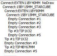
I'd like the ability to change the contents of a probe file without having to reconstruct the entire probe build. We have 15 production machines and are trying to simplify the process of changing a broken stylus. An under trained person won't know that a 4 x 67mm custom stylus is ITP part number STHM504011069.
If I could just edit the stylus names in the existing probe files in a text file format it would be much easier than having to create all new probe files.

tesselation of probe
Hi,
Many user change the open GL tesselation value to 1 -> 0,1.
It would be great some possibilities that the Probe ball and shaft tesselation also can to improve...
Thanks in advance!

Make it possible to delete hits from measured features from within the hits dialog
Like the title.
I use measured features a lot (placing hits with mouse/joystick) especially on surfaces/planes.
I have found it quite cumbersome to delete a certain hit from the feature, as you first need to
"find" the hit - either in the command or by using the "hits" dialog for measured features:
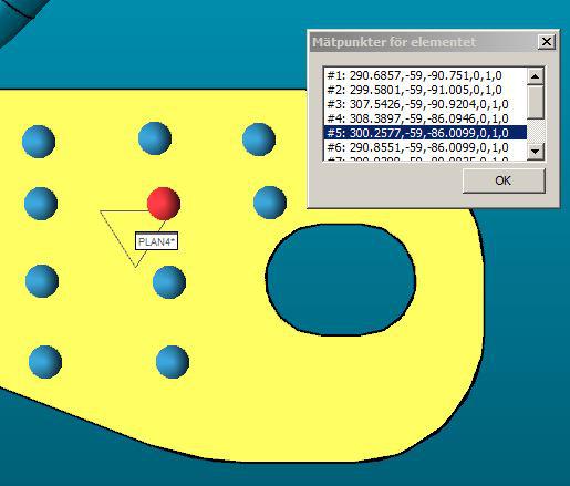
After that, you will need to find the actual hit in the command and remove it.
Then, repeat the procedure until all the hits you want to remove are gone.
I would like to have the possibility to multi-select the points I want to remove
through the dialog shown in the image.

3d rotation mode for clip plane
Have a 3d rotation mode for clip planes. It would make it much faster to cut away the stuff you don't want to see if you had a graphic you could drag around. Maybe have handles you could translate in X, Y or Z and other handles so you could rotate the clip plane in I, J, and K.
Shift nominals of selected features
The ability to select several features and shift the nominal in any axis.
For Example Two Spheres on a Bar. New revision change makes the bar 1mm longer. Lets assume one of the spheres is 0,0,0. I could select the feature(s) and move their coordinates in the desired direction.(Nominal, theo, target - perhaps a toggle for each). A lot of times this can be done by manipulating alignments, but not always and this is much simpler.
I could also see the ability to grow or shrink a group of features by 'x.xx' as useful as well. A lot of parts have families with only minor changes and lots of similarities.

Probe Utilities - Setup - Clearance Distance - In Z
Probe Utilities - Setup - Clearance Distance -
In Z when qualification tool shank is perpendicular to Z axis: - This item defines the clearance distance in the Z axis when the qualification tool's shank is perpendicular to the Z axis. When the qualification tool is mounted on a horizontal shank, it sometimes needs extra Z clearance movement, especially on horizontal arm machines, to avoid collisions. The measurement units are the same as those used by your measurement routine.
This Clearance distance setting will move the probe after calibrating selected tips. Add the ability to use this setting to move the probe before and after calibrating selected tips.
Customer support service by UserEcho
