Hexagon Measurement SystemsNo matter what Hexagon measurement equipment or software you use, we want to hear your ideas and suggestions on how we can improve.
Thanks for your assistance in helping us shape the future. |
|


 Hydraulic Valve Cavities and O-Ring Port Module Needed
We run many manifold blocks with many Hydraulic Valve Cavities and O-Ring Ports, it would be nice to have a module either with many of the standard sizes or at least where we could build up the sizes we need and then be able to save and keep these for other parts.

Show max/min value when evaluating the position of a plane (ISO 1101)
When evaluating the position of a plane, have the ability show the max & min value.
Basically like its done with the surface profile.
It helps to quickly see if the whole plane is offset or if there is a form or angle error.

Automatically Update Cad Vectors
When I import the XYZ & feature ID for several hundred points which do not contain IJK values, I would like to automatically update the vector for all of them. I would like to see an option to automatically update vector points without having to open each individual vector point.

Global dimension color
Ability to change the report dimension colors globally.
Currently there is only the option change the active program and set the default for new programs. There is no option to globally change all reports for programs that are already created.

Tip selection option in jog box (OR) Single click auto circle pick option by using Star probe
During the manual measurement ,we don't have the option to select the tips from the jog box, instead of that every time we need to select the tips from the software screen.
For fixed probe head user this option would be very use full for circle and point measurement. Every time we no need to go to the screen for tip selection.
Or else you can introduce the auto circle selection from the CAD by using star probe so that we can define the no tips and we can add the safe moves.

Inspect Pallet execution cell failure unexpected hit or probe missed part error handling and continuation.
Add possibly two modes of error handling whenever a cell part is not fixtured correctly.
1. Advance to next cell and keep all index/counter trace fields sequenced correctly to cell. This would be best for operator environments.
Allow only the bad cells to then be rerun after correction maintaining trace field sequence as noted.
As they can currently select cells for execution, the trace field sequence is the the important piece.
Also, if they are running successive fixtures, allow for control of Index/counter trace inputs, stop start or override with specific cell value.
2. Create or use existing notification tools to text programmer, or set stack/message light status to raise awareness.
Allow programmer to reset poorly fixtured part and resume execution from that cell maintaining trace sequence as previously stated.
Multiple sequential playlist execution with index counter trace field sequencing.
This appears to be similar to one Lupe added previously.
In lieu of a multi-fixture sequential execution, provide a means of controlling count and/or prompting for next fixture load. Also, it would be important for index/counter trace fields to be sequence with fixture/cell.

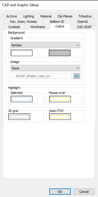
Change Label Colors
I would like to be able to change the colors, both background and line colors, from the standard PC-DMIS labels.
There is already a possibility to change colors related to the view and other functionalities. Perhaps this menu can include the reporting label colors.
In this menu you could then select the standard PC-DMIS label colors and change them to your company colors.
Currently we are changing every single label manually to adjust them to our company colors (blue lines will be black en the background colors will match our company's colors).
This takes a extremely long time, but with this option mentioned above everyone could change it instantly to their own liking, with the possible added benefit that your reports match your company colors for professionalization.

Find hole available for concentric cilinder scan (Auto element)
Within the auto elements of the circle we have the option find hole with adaptive circle scan. Unfortunately this is not possible for concentric circle scan in the auto element of the cilinder.
It would be an advantage if the "find hole" option would be available for the concentric circle scan of the auto-element cilinders.

Service d'assistance aux clients par UserEcho
