Hexagon Measurement SystemsNo matter what Hexagon measurement equipment or software you use, we want to hear your ideas and suggestions on how we can improve.
Thanks for your assistance in helping us shape the future. |
|

 CAD Translation Improvement
When translating a CAD model be able to select a feature and tell the software to rotate to a specific direction. Select feature, Rotate to "specific direction" , OK and DONE

 Option to Delete items referenced by commands within the pop up notification
When deleting a feature in the edit window (e.g. an auto surface point), if that data point has a dimension associated with it, a pop up occurs asking "The following commands reference one or more items you are about to delete: xxxyyyzzz Are you sure you want to delete these commands?"
Add an option within that pop up, to delete the referenced commands "Yes or No", with a default answer allowed in the setup. This would eliminate having to go through the routine after deletion and find the dimension, alignment, variable, etc. to delete the referenced command as well as the feature just deleted.
This would also help to mitigate the later opening of routines that give the error upon opening "the following dimensions have no feature id".

 Constructed circle tangent to 2 circles
Hello
Being able to make a constructed circle tangent to 2 circles by imposing the diameter would be useful. For the dimensions on gable pins with rounded teeth for example… This exists with tangent to 2 straight lines so why not 2 circles…
Cordially,

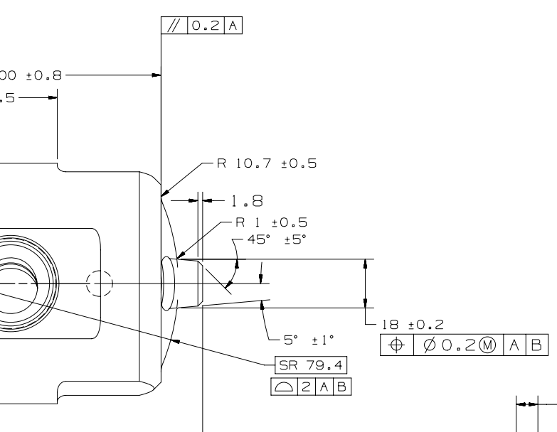
 In construct circle, need an auto cone to pierce an auto sphere and construct a circle where it pierces it
In construct circle, need an auto cone to pierce an auto sphere and construct a circle where it pierces it
Below shows the cone piercing the Sphericle radius to get the Ø18 (the Print is missing the diametrical symbol)


 FBM (Feature Based Measurement) add as a Standard Module for PC-DMIS
FBM (Feature Based Measurement) should be added as a Standard Module. Currently this option is only available if your PC-DMIS license is programmed with the Feature Based Measurement module.
2022.1 Help file - Using Feature Based Measurement
The Feature Based Measurement (FBM) method is an optional feature in PC-DMIS. FBM functionality is only available if your PC-DMIS license is programmed with the Feature Based Measurement module.
FBM offers collision-free measurement of any dimension in a measurement routine.
Mini routines provide the user interface that enables you to execute a measurement routine that you create with the FBM method. Sub mini routines provide the facility to create the structure to measure tool-based, cell-based, and operation-based features from the measurement routine.
FBM is useful in situations where you want to do the following:
- Create a measurement routine for a complete, manufactured part and still be able to use the same measurement routine to measure the part, or a single feature, after each operation
- Quickly measure only selected features; for example, you may want to change tools on a fully-automated manufacturing line
- Run a partial measurement routine
For more information on FBM:
2022.1 Help file link
PC-DMIS User Forum link

 Trace field dialog resize
When we use trace field for input general data about parts which we measure. Trace field dialog shows up on screen. Dialog can be resized only in left and right side, but it can't be resize for up-down?!. When we have a lot of trace fields we need to use scroll bar, and this is waste of time, and that is not very user friendly. Please make change and dialog that can be resized in both direction.

 Schedule program
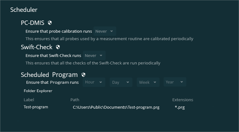
In inspect 5.1 we have been given the opportunity to schedule a calibration or Swift check. could it be possible to extend the "schedule" function so it becomes possible to schedule a specific program to run every hour, day, week or year.
see example:


 Allow serial number for each pallet cell to be scanned on barcode
In Inspect, the serial numbers (or other trace) can be entered in the pallet screen prior to measurement.
It would be useful to have an option where the serial number for each cell could be scanned in using barcode, to make this process more efficient and less error prone
Filed on behalf of a customer.
Service d'assistance aux clients par UserEcho


