Hexagon Measurement SystemsNo matter what Hexagon measurement equipment or software you use, we want to hear your ideas and suggestions on how we can improve.
Thanks for your assistance in helping us shape the future. |
|

 Combine the Laser tab with the readout window for the HP-OW going forward.
With the launch of the new HP-OW, could we get the laser tab and the probe readout window combined? Some folks use the Chroc box to view the graph and now it will be closed up in a box on the side of the machine. Some use the probe readout to view the distance and intensity. It would be a nice go between.

 Excel Form Report Option to not report skipped dimensions
Currently, It appears that an unmarked or skipped feature will still report to the form report. The dimension must also be unmarked, then that dimension is not reported. I would like the option to not report skipped features.

 Report a 2D perimeter of multiple circle scans
PC-DMIS should get a function to take multiple circle scans (or other scans) and join them together to create a perimeter. There should also be a reporting button to make an easy process.

 Ability to manage speed of simulation
I would be so handy if the speed of simulation in off-line mode is manageble over a slide by mouse or by arrow up / down buttons. So I can high-speed trough for example a multi-hole pattern.

 CAD graphics improvement
Need to see flipped normals without having to click reverse cad faces first

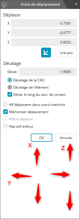
 Move Point Feature jog mode offline
Add a jog button to move the point in off line mode
to be easier to add clerance point, jump jigs, avoid collision, etc
thanks

Servicio de atención al cliente por UserEcho


