Hexagon Measurement SystemsNo matter what Hexagon measurement equipment or software you use, we want to hear your ideas and suggestions on how we can improve.
Thanks for your assistance in helping us shape the future. |
|


 Make an option in Inspect to have the barcode in Inspect linked to a COM port
When you have the barcode option linked to a COM port, then it always checks if there is an input from the barcode reader. Even if you're not in the input field for Inspect. With the link to a COM port, you are always sure that the routine starts.
Currently there is a hardware keyboard wege and sends the input from the barcode reader to the keyboard. It would be nicer if there is a software keyboard wedge. A software keyboard wege connects directly to the COM port and not the keyboard. Data from the barcode scanner is sent to the COM port and is rerouted to the keyboard buffer. This way you're sure that Inspect is always reading the input from the barcode scanner even if you're in another input field.

True position tolerance add on - In Use Legacy Dimension
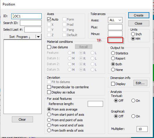
Dear Team,
During the position tolerance callout, we don't have the separate column for position tolerance update . Instead of that every time we modifying in report callout.
In addition to +/- tolerance, if you provide the position tolerance column it would be very useful.
If any other method available in current state, please let me know.
Regards
Srinivasan N

Hydraulic Valve Cavities and O-Ring Port Module Needed
We run many manifold blocks with many Hydraulic Valve Cavities and O-Ring Ports, it would be nice to have a module either with many of the standard sizes or at least where we could build up the sizes we need and then be able to save and keep these for other parts.

Show max/min value when evaluating the position of a plane (ISO 1101)
When evaluating the position of a plane, have the ability show the max & min value.
Basically like its done with the surface profile.
It helps to quickly see if the whole plane is offset or if there is a form or angle error.

Increase Edit Window scroll speed
Scrolling through the Edit Window with the scroll wheel on the mouse is very slow, only about three lines per scroll. Can there be an option in the software to increase the scroll speed?

Automatically Update Cad Vectors
When I import the XYZ & feature ID for several hundred points which do not contain IJK values, I would like to automatically update the vector for all of them. I would like to see an option to automatically update vector points without having to open each individual vector point.

Global dimension color
Ability to change the report dimension colors globally.
Currently there is only the option change the active program and set the default for new programs. There is no option to globally change all reports for programs that are already created.
Tip selection option in jog box (OR) Single click auto circle pick option by using Star probe
During the manual measurement ,we don't have the option to select the tips from the jog box, instead of that every time we need to select the tips from the software screen.
For fixed probe head user this option would be very use full for circle and point measurement. Every time we no need to go to the screen for tip selection.
Or else you can introduce the auto circle selection from the CAD by using star probe so that we can define the no tips and we can add the safe moves.

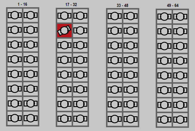
Inspect Pallet execution cell failure unexpected hit or probe missed part error handling and continuation.
Add possibly two modes of error handling whenever a cell part is not fixtured correctly.
1. Advance to next cell and keep all index/counter trace fields sequenced correctly to cell. This would be best for operator environments.
Allow only the bad cells to then be rerun after correction maintaining trace field sequence as noted.
As they can currently select cells for execution, the trace field sequence is the the important piece.
Also, if they are running successive fixtures, allow for control of Index/counter trace inputs, stop start or override with specific cell value.
2. Create or use existing notification tools to text programmer, or set stack/message light status to raise awareness.
Allow programmer to reset poorly fixtured part and resume execution from that cell maintaining trace sequence as previously stated.
Multiple sequential playlist execution with index counter trace field sequencing.
This appears to be similar to one Lupe added previously.
In lieu of a multi-fixture sequential execution, provide a means of controlling count and/or prompting for next fixture load. Also, it would be important for index/counter trace fields to be sequence with fixture/cell.
Servicio de atención al cliente por UserEcho
