Hexagon Measurement SystemsNo matter what Hexagon measurement equipment or software you use, we want to hear your ideas and suggestions on how we can improve.
Thanks for your assistance in helping us shape the future. |
|

 please add Tracker Pilot for AT40x to the supported software
Please add Tracker Pilot for AT40x to the supported software list, so that we can get rid of leica update manager and so that legacy users can download the last version in the future, from the "universal" new platform.
Thank you!

 Remove non-applicable checkboxes and items from Probe Utility based on sensor type and settings
Our Probe Utility Dialog has not really changed to the better as new releases are made. I suggest efforts are placed into enhancing one dialog which is so critical to end users.
One critical change in my view is for us to remove any checkboxes and displayed tags that do not apply to the currently opened Probe. And present them as applicable.
One big/huge example are the checkboxes for Use Partial Calibration and Use Trax Calibration.
Use Partial Calibration is pretty much exclusive to SP25 scanning probes. Why present/show, even if grayed out this box to a user that might be using Camera, Laser, Touch trigger probe, etc?
TRAX calibration is exclusively for analog scanning probes and only applies to certain probes and controllers. This info is known to us. We know which controllers (interface and Settings) have or need this calibration type.
We gray this checkbox out w/ a checked or unchecked condition because it is not applicable. Why display it?

Our Probe Utility dialog offers tons of opportunities not only for improvement but for a better User Experience.
Its redesign is well past due.

 Export XZY file automatically
The customer always has to manually export his XYZ file (File - Export - XYZ).
He would like to be able to write a command into the program so that it works automatically.

 average tp in report
we have a part where we measured the TP (true position) of 10 (or more) circular features...does anyone know if it can be done or how to output the "average" TP on the reports and excel files (not vector, just straight average of the TP out of tolerance values)?

 Allow sharing of multiple samples
Second idea is the possibility to Filter and Share a whole page of samples, i.e., we want to send to a client all the measurements for a range of samples of a part, instead of having to select one by one and share...

 Add "Dashboard Summary" tab with important information across ALL parts
It would be nice to have an overall dashboard (homepage) for all parts. The insights is nice on the right hand side of the page but it would be nice to have a homepage that goes over any quality issue notifications and has charts for all parts, similar to the part summary but for all parts.

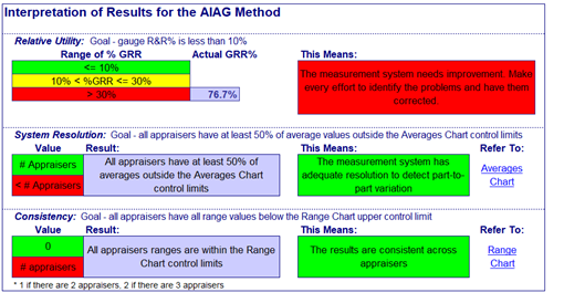
 Add Gage R&R support into Metrology Reporting
It would be cool to see some features of gauge r and r implemented into metrology reporting.

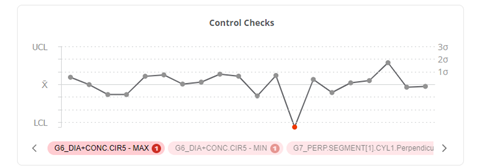
 Have a way to auto cycle control charts
It would be good if the control checks chart automatically move between the different control checks every few seconds (like a slide show).

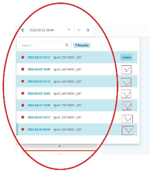
 Allow previous runs of a specific sample to be ignored for statistics
Dear sirs,
i have 2 recommendations (if not implemented on pro version):
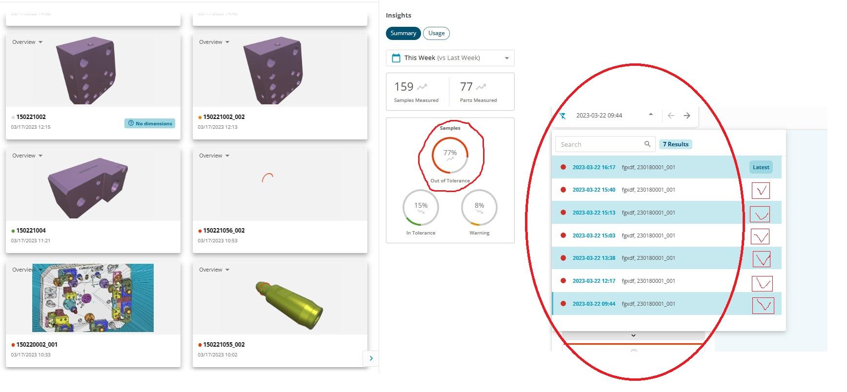
The idea is to have the possibility to engage or not previous measured samples, why? Because in certain situations we don't want to consider the several times that the same program runned as different parts with same reference, that is, in the case of an iterative measure and tunning of an assembly we just want to consider the last one for the general statistics...
Kundesupport af UserEcho
